YO EverLink Pro – LoRaWAN Gateway
This guide will help you set up and manage your LoRaWAN YO EverLink Pro efficiently. Whether you are deploying a single YO EverLink Pro or managing multiple, this page provides all the key details.
Overview
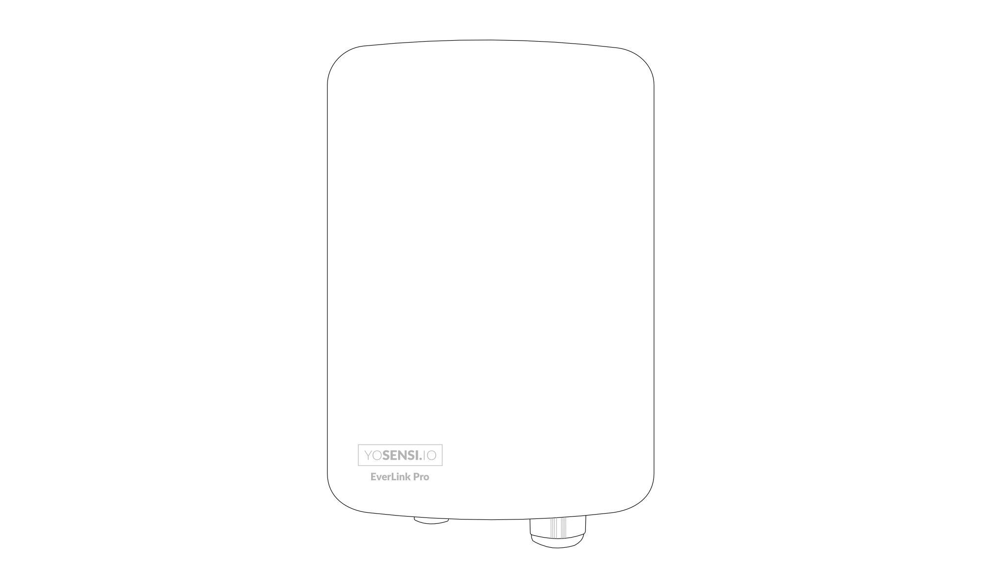
Figure 1. YO EverLink Pro top view
- Model: YO EverLink Pro
- Frequency Band: EU868, US915, AU915, AS923
- Connectivity: Ethernet, Wi-Fi, Bluetooth, Cellular, LoRaWAN
Key Features and Management
Management Options
- Cloud Management: Remote management via the Yosensi Cloud Platform (https://cloud.yosensi.io/).
- Local Management: On-device web interface, available through the gateway’s IP address.
- Yosensi Mobile Application: Currently supports gateway adoption and basic network interface configuration.
Monitoring and Diagnostics
The Yosensi Cloud Platform reports the gateway's current state on its overview page. The table below summarises the main values; the platform provides further detail for each.
| Group | Reported values |
|---|---|
| Device | Firmware version, ChirpStack Gateway Bridge version, uptime, power source |
| System | CPU load, memory usage, disk usage, PCB temperature |
| Network | Active interface, and data usage for Ethernet, Wi-Fi and mobile |
| Cellular | SIM status, mobile network and signal quality |
| LoRaWAN | Packet statistics, TX collisions, signal strength (RSSI/SNR) and packet logs |
Firmware Updates
- Update YO EverLink Pro firmware to the latest version for improved performance and security.
Security Features
- Account-based access: the gateway is managed from your Yosensi Cloud Platform account. Access is controlled by your own account credentials.
- Device identifier: each gateway carries a unique LoRa concentrator ID. It identifies the unit only — it is not a credential and is not used to authorize the gateway.
- Ensure secure and convenient management through Cloud Management or Local Management.
Specifications
Physical
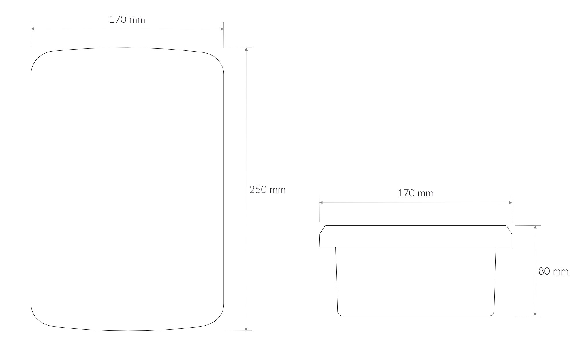
Figure 2. Dimensions of the device
Device
| Attribute | Description |
|---|---|
| Hardware version | 1.0 |
| Firmware version | 1.0.0 |
| Dimensions | Height: 60 mm Width: 145 mm Depth: 210 mm |
| Colour | White |
| Mounting method | Horizontal (brackets) Pole (brackets) |
| Enclosure material | ASA |
| Level of protection | IP68 |
| Weight | 314 g |
| Service/Boot port | USB-C |
| Wi-Fi | 2.4/5.0 GHz 802.11a/b/g/n/ac |
| Bluetooth® | v5.2 |
| Cellular (optional) | LTE Cat 1 bis (3GPP Rel. 14) Downlink: 10 Mbps / Uplink: 5 Mbps |
| Cellular Bands | LTE FDD: B1, B2, B3, B4, B5, B7, B8, B12, B13, B18, B19, B20, B25, B26, B28, B66 |
| SIM card | Nano SIM (4FF) |
| Ethernet | 10/100Mbps IEEE802.3/802.3u |
| Expansion storage | microSD card slot |
| Accelerometer | 3-axis – device rotation and placement |
| Internal sensors | Enclosure temperature and humidity |
| Antennas | LoRa: internal or external Cellular: internal or external Wi-Fi/Bluetooth®: internal |
Ordering Options
The YO EverLink Pro is configured at order time. The following options are available.
| Option | Choices |
|---|---|
| LoRa antenna | Internal or external |
| Cellular antenna | Internal or external |
| Cellular modem | With or without |
| Supercapacitor backup | With or without |
Operating Conditions
| Attribute | Description |
|---|---|
| Temperature | 0°C to 55°C |
| Humidity | 0 to 90% |
| Placement | Indoor/Outdoor |
| Power supply | JACK 5.5/2.1 24 V DC RJ45 PoE (standard 802.3af / 802.3at) |
| Power consumption | Maximum: 300 mA DC (24 V DC) Maximum: 1500 mA DC (5 V DC) PoE: 1.5 W average, 7.5–8 W maximum |
| Backup power (optional) | Supercapacitor – 90 seconds of operation after mains power is lost |
Controls and Indicators
LED and Buzzer Status Indicators
The YO EverLink Pro reports its state through a status LED and a buzzer. Both are visible and audible with the enclosure closed, and together they cover everything an operator needs during normal use.
Status LED
The status LED is always solid — it never blinks. The colour tells you what is happening.
| Colour | Meaning | What to do |
|---|---|---|
| Off | No power, or the device has just been switched on | If it stays off for more than a minute, check the power supply |
| Yellow | Starting up or shutting down | Wait — startup takes about a minute |
| Green | The gateway is running, but has no internet connection | Check the Ethernet cable, SIM card or Wi-Fi |
| Blue | The gateway is running and has an internet connection — normal operation | Nothing |
| Red | Fault — the gateway is not working correctly | Restart with a short press of the button. If red returns, contact support |
- Off
- YellowOne short beep
- Green
- BlueOnce the internet connection is established
- YellowA double beep
Blue is the target state. A healthy gateway settles on blue and stays there.
Buzzer
The buzzer follows one rule: rising tones mean something was gained, falling tones mean something was lost. Connection and power signals are symmetrical pairs, so you can tell what happened without memorising individual patterns.
Bar height is frequency and bar width is duration, on one time scale shared by every row. Select a signature to hear it.
| Signature | Signal | Meaning |
|---|---|---|
| Startup | ||
| Bootloader startedOne short beep | The bootloader has started. The device is loading the system. | |
| Faults | ||
| System errorTwo long, equal (with red LED) | System error. Critical services are not running. Restart the device. | |
| System shutdownTwo short, rapid | The device is restarting or shutting down. | |
| Connectivity — a mirrored pair | ||
| Device onlineThree rising tones | The device has an internet connection. | |
| Device offlineThree falling tones | The device has lost its internet connection. | |
| Power — a mirrored pair, in the order an outage happens | ||
| Power lostFour falling tones | Power lost. The device is running on the supercapacitor. | |
| Running on supercapacitorOne long beep, repeating | The device is still running on the supercapacitor. | |
| Power restoredFour rising tones | Mains power restored (PoE or power adapter). | |
Service Indicators (Internal)
The following LEDs sit on the PCB and are visible only with the enclosure open. They are intended for service and diagnostics rather than day-to-day operation. Figures 3 and 4 show their placement.
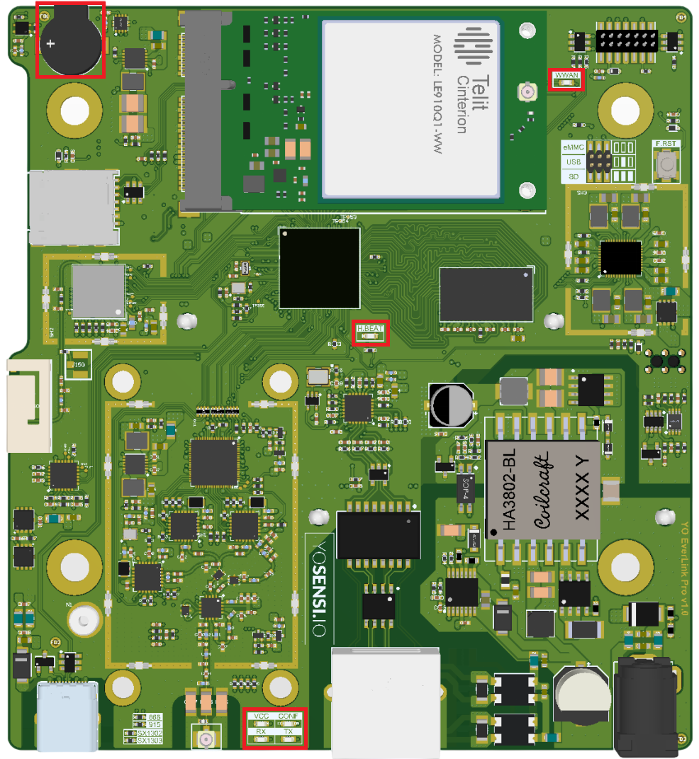
Figure 3. YO EverLink Pro PCB - Front View
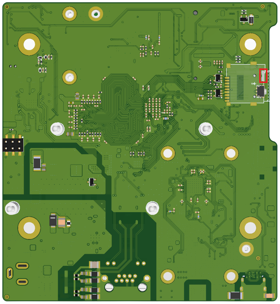
Figure 4. YO EverLink Pro PCB - Back View
RX LED
| Behavior | Colour | Status |
|---|---|---|
| Flash per packet | Green | General: The SX1302 concentrator has received a LoRaWAN packet. |
TX LED
| Behavior | Colour | Status |
|---|---|---|
| Flash per packet | Green | General: The SX1302 concentrator is transmitting a LoRaWAN packet. |
CONF LED
| Behavior | Colour | Status |
|---|---|---|
| Continuous | Green | SX1302 concentrator has been configured. |
VCC LED
| Behavior | Colour | Status |
|---|---|---|
| Continuous | Green | General: Modem LoRaWAN is working correctly. |
HBEAT LED
| Behavior | Colour | Status |
|---|---|---|
| Heartbeat flashing | Green | General: CPU is working correctly. |
WWAN LED
| Behavior | Colour | Status |
|---|---|---|
| Continuous | Green | General: Telit module is initialized correctly. |
Buttons
The YO EverLink Pro has two buttons, both on the PCB inside the enclosure — the enclosure has to be open to reach either of them.
| Button | Press | What happens |
|---|---|---|
| Restart button back of the board | Press | The gateway restarts. Nothing else changes. |
| F_RST front of the board | Short press, released before 5 s | The gateway restarts. Nothing else changes. |
| F_RST front of the board | Hold for at least 5 s, then release | Soft factory reset — all settings are cleared. Installed firmware updates are kept. |
| F_RST front of the board | Hold before connecting power, and for at least 5 s after | Hard factory reset — firmware is restored from the recovery partition. |
Both buttons can restart the gateway, but only the restart button is a hardware reset, so only it is guaranteed to work. If the gateway is unresponsive, use the restart button on the back.
Restart button (back of the board)
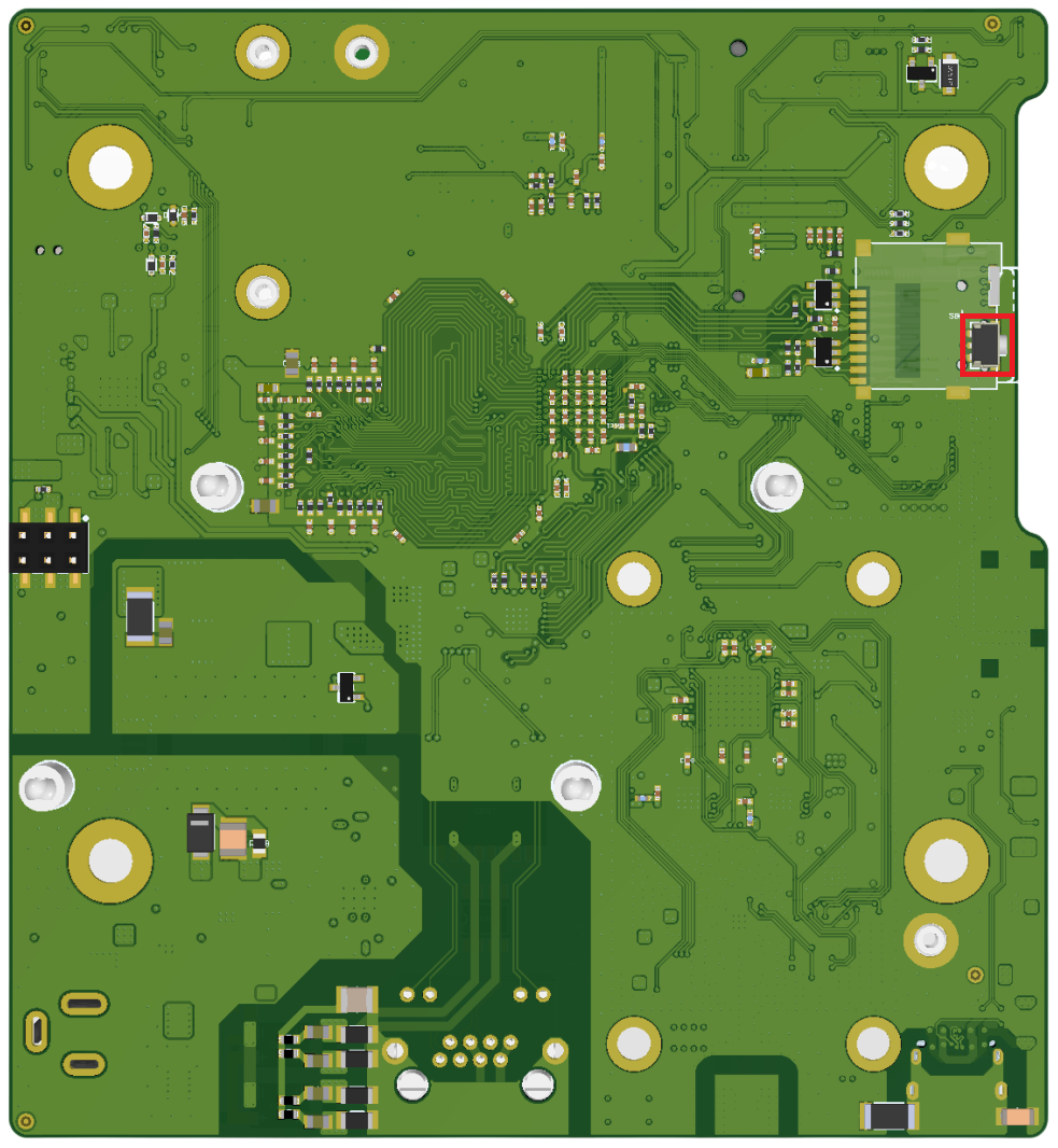
Figure 5. Restart button - back of the board, below the SIM card slot
The button sits below the SIM card slot. It carries no silkscreen marking, so use Figure 5 to locate it.
A press restarts the gateway. Nothing else changes — settings, keys and firmware are all kept.
This is a hardware reset: it acts on the processor directly instead of asking the software to restart. It therefore works even when the gateway has stopped responding, for example after a software crash. It is the button to use when F_RST does nothing.
F_RST while the gateway is running
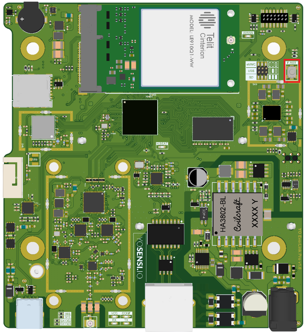
Figure 6. Reset button (F_RST) - front of the board
A short press restarts the gateway. Holding F_RST for at least 5 seconds triggers a soft factory reset, which clears all settings. Firmware is not restored from the recovery partition, so installed firmware updates are retained.
The action starts when F_RST is released, not while it is held. There is no LED or buzzer confirmation either way.
F_RST is a programmable button, so both actions are carried out by the software. They only work while the system is still responding — if the gateway has crashed, F_RST does nothing and you need the hardware restart button on the back of the board.
A long press erases all settings. Release F_RST before 5 seconds have passed if you only want to restart the gateway.
F_RST during power-up — hard factory reset
A hard factory reset restores the firmware from the recovery partition. Use it only when a soft factory reset has not resolved the problem.
To start it, hold F_RST before connecting power, and keep holding it for at least 5 seconds after power is applied.
The operation takes several minutes. Do not disconnect power while the restore is running.
What to expect:
- A single short beep sounds shortly after power-on. It confirms only that the device has started — not that the restore is running.
- The LED stays solid yellow for the whole operation. There is no progress indicator and no further sounds.
- When the restore finishes, the gateway restarts itself. This happens once during the whole procedure.
- After that restart the gateway starts normally: yellow → green → blue once it has an internet connection. This first start-up takes longer than usual, because the gateway prepares its memory again.
The gateway is ready once the LED turns green or blue.
If the LED is still yellow after about 15 minutes: disconnect power, wait 10 seconds, then reconnect without holding F_RST. If that does not help, contact support.
Initial Setup
-
Physical Installation:
- Mount the YO EverLink Pro in a location with optimal coverage and minimal interference.
- Ensure proper power supply and environmental conditions.
-
Network Configuration:
- Connect the YO EverLink Pro to your network (Ethernet, Wi-Fi, or Cellular).
- Configure the network settings (IP address, DNS, etc.) via Local Management or the Yosensi mobile application.
-
YO EverLink Pro Activation:
- Log in to the gateway's web interface.
- Register the YO EverLink Pro on your LoRaWAN network server (LNS) using:
- YO EverLink Pro EUI (unique identifier).
- Network server credentials.
Installation and Placement
Proper installation and placement of the YO EverLink Pro are essential for optimal performance. Below are the recommended mounting methods and guidelines.
Available Mounting Methods
- Horizontal Mounting
- Use the provided brackets to securely mount the YO EverLink Pro on a flat horizontal surface, such as a shelf or a server rack.
- Ensure the surface is stable and free from vibrations.
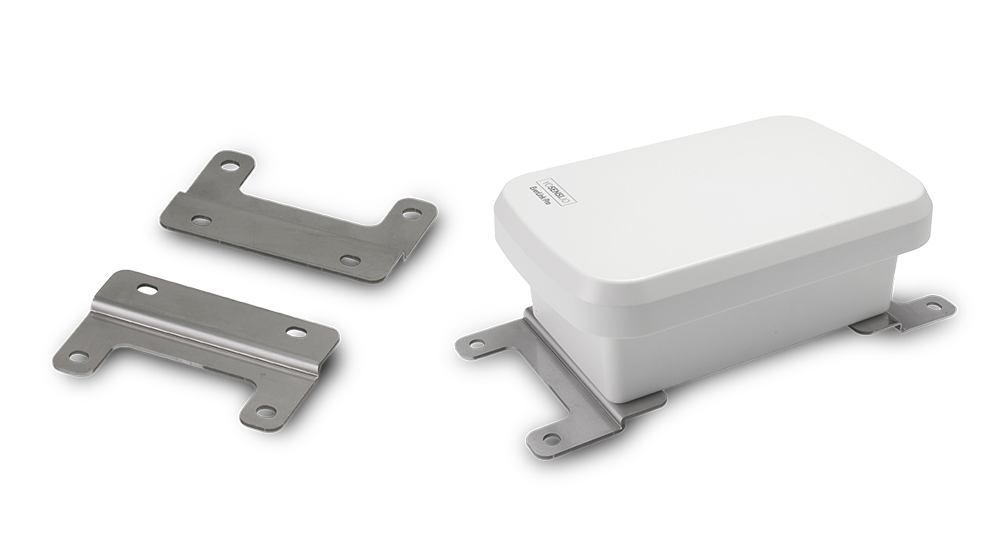
Figure 7. Horizontal mounting method
- Pole Mounting
- Attach the included pole brackets to mount the YO EverLink Pro on a vertical pole.
- This method is ideal for outdoor installations where height improves signal coverage.
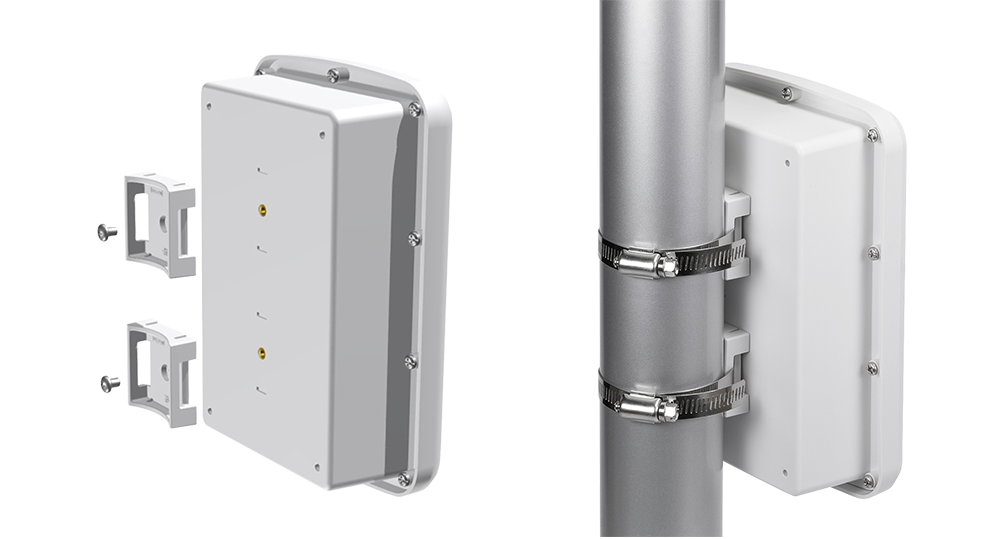
Figure 8. Pole mounting method
Installation Tips
-
Optimal Placement:
- Choose a location with minimal physical obstructions to ensure clear signal transmission.
- Avoid placing the YO EverLink Pro near sources of interference, such as large metal objects, electrical equipment, or dense foliage.
-
Environmental Considerations:
- Ensure the YO EverLink Pro is installed within the recommended operating temperature and humidity range.
- For outdoor installations, confirm the mounting area is weatherproof or within the gateway's IP68 protection limits.
-
Power Supply:
- Place the YO EverLink Pro near an accessible power source or ensure a PoE-capable Ethernet connection.
Mounting Accessories
| Accessory | Description | Usage |
|---|---|---|
| Horizontal Brackets | Pre-installed brackets for secure horizontal mounting | Indoor or flat-surface installations |
| Pole Brackets | Adjustable brackets compatible with various pole diameters | Outdoor or elevated installations |
Troubleshooting
Common Issues
- Connectivity Problems:
- Check network cables or Wi-Fi settings.
- Verify YO EverLink Pro EUI registration on the LNS.
- Device Not Connecting:
- Confirm device configuration (DevEUI, AppKey, frequency plan).
- Ensure the YO EverLink Pro is within range and signal is not obstructed.
- Data Not Forwarding:
- Check server credentials and integration settings.
Logs and Diagnostics
From Cloud Management or Local Management you can:
- Access system logs with detailed error messages.
- Use diagnostic tools to test network and radio functionality.
Support and Maintenance
- Scheduled Maintenance:
- Regularly check for firmware updates.
- Clean the YO EverLink Pro and check for physical damage.
- Support Contact:
- For support contact us at support@yosensi.io