YO Airflow Pro
Overview
Description
YO Airflow Pro is a differential pressure measuring device, used for application i.e. to verify the degree of air filter contamination, and control the pressure in air conditioning systems and air blowers. Also can be used for airflow control and monitoring.
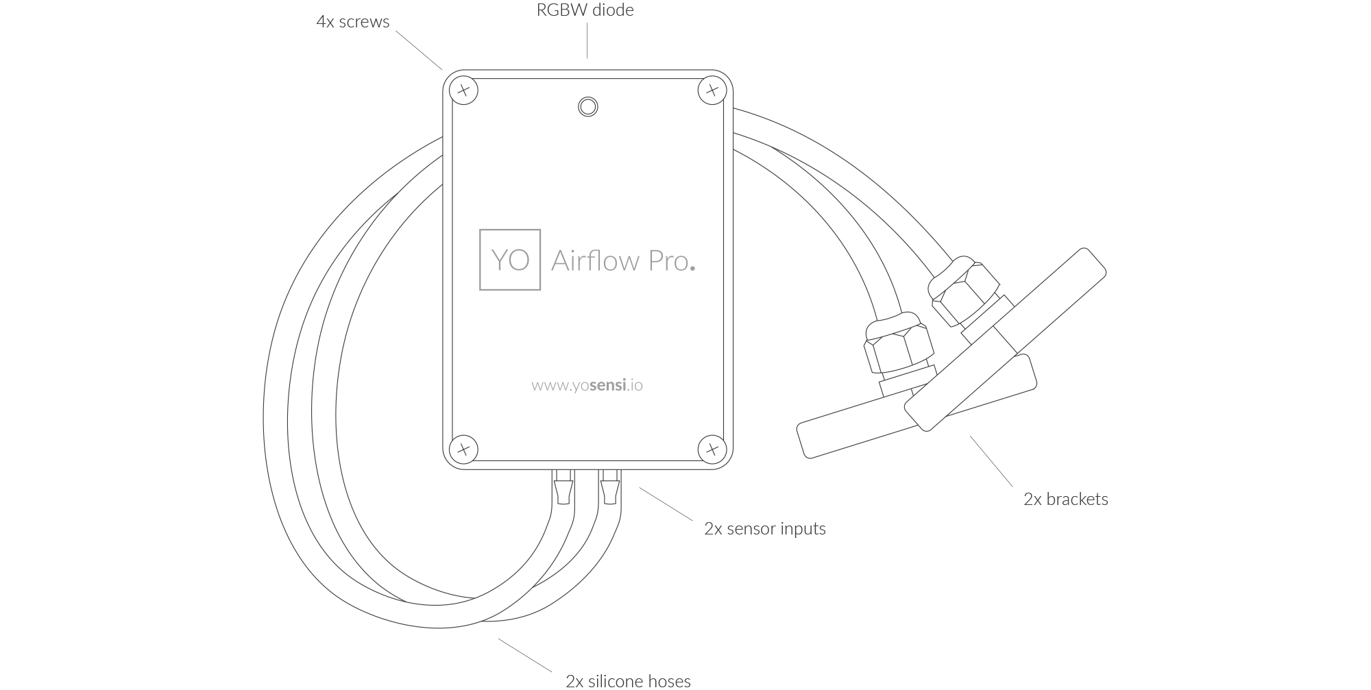
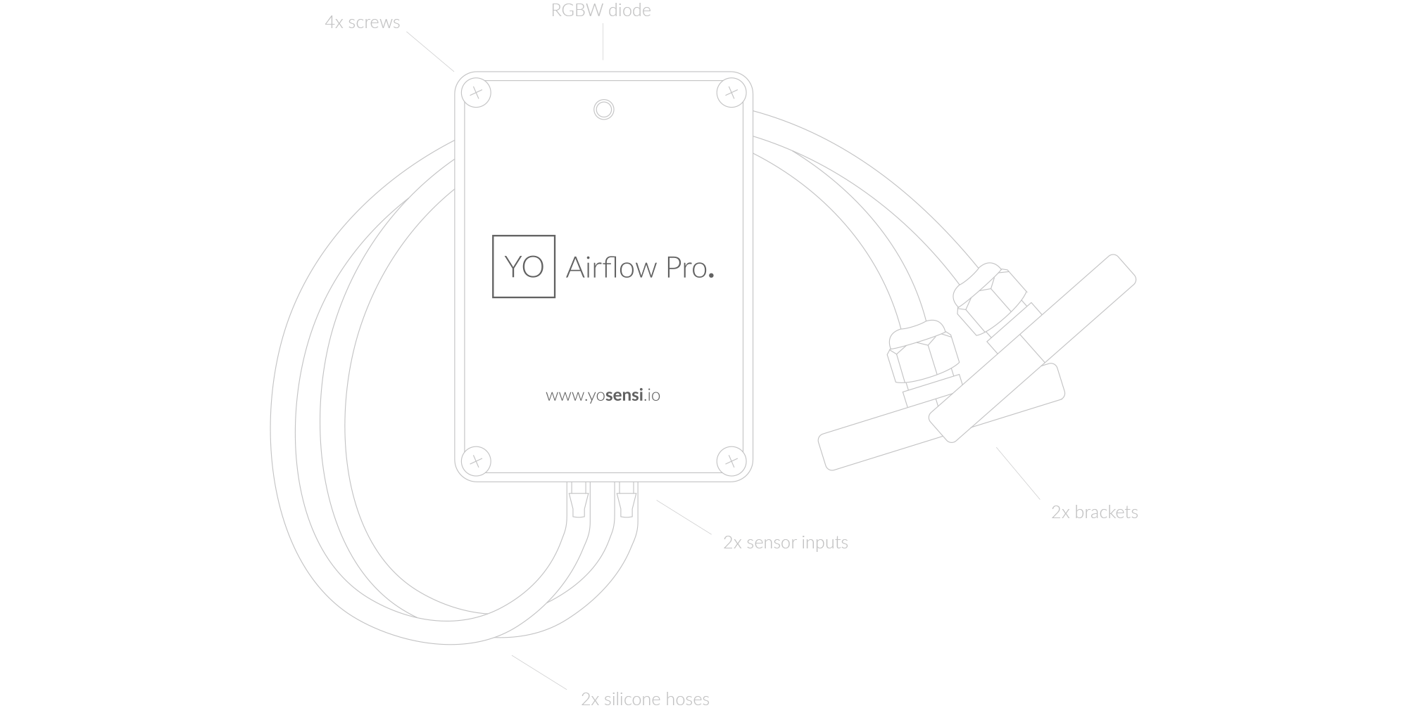
Figure 1. Device top view
Device sticker placed on the right side of the device enclosure contains information about model, version, LoRaWAN region and 3 parameters important in case of device identification and configuration:
- DEV EUI: 64-bit unique device identifier in a LoRaWAN network,
- DEV ADDR: address required to connect via ABP activation type to LoRaWAN,
- BLE MAC: Bluetooth physical address.
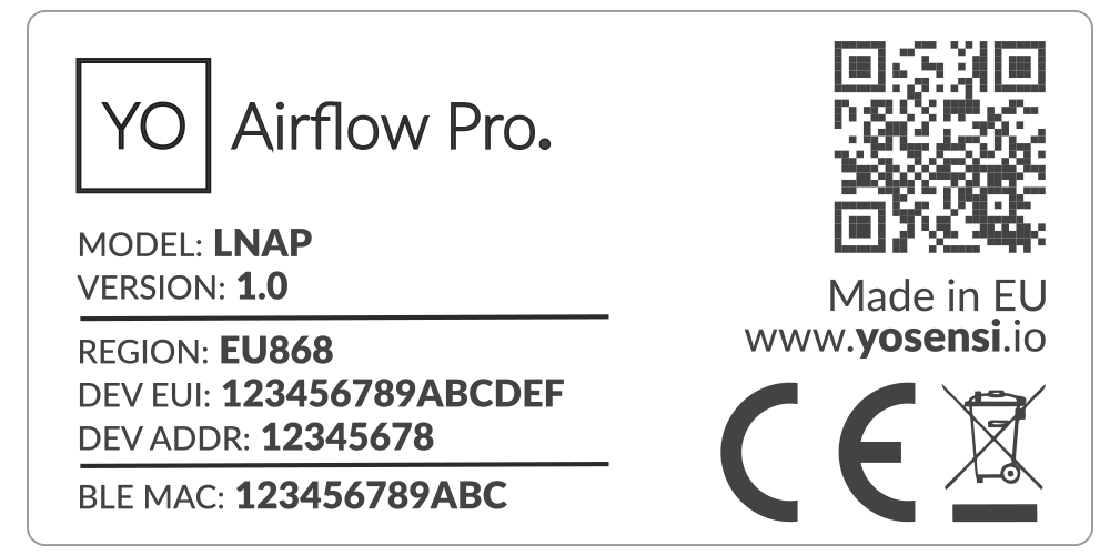
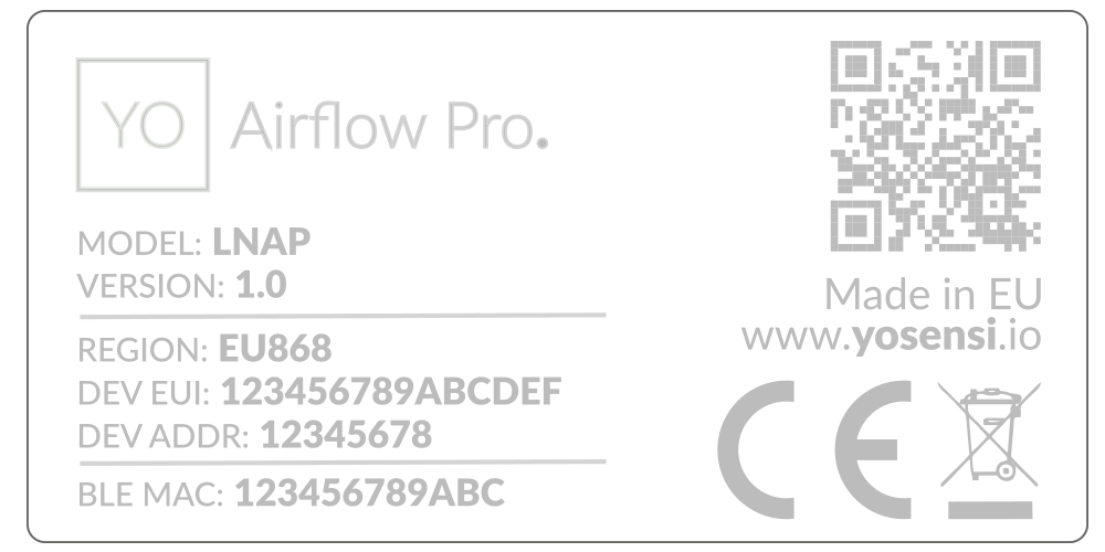
Figure 2. Device sticker
Features
- LoRaWAN Technology: Available in multiple versions with LoRa radio configured for various regions and ISM frequency bands (e.g., EU868, US915, AU915), it is compatible with both private and public LoRaWAN networks and supports connections via ABP (Activation by Personalization) or OTAA (Over-The-Air Activation).
- Bluetooth Low Energy (BLE): Enables easy configuration through a user-friendly JSON data exchange format, supports firmware updates via OTA (Over-the-Air), and boasts very low energy consumption.
- Battery-Powered: 3x AA lithium batteries featuring very low self-discharge, ensuring long-term operation without the need for an external power supply.
- Temperature and Relative Humidity: Measures temperature and relative humidity within the device enclosure, providing valuable insights into the surrounding environment.
- Differential Pressure: Measures airflow using dual compartments to ensure air quality. Sudden drops in pressure charts indicate worn or clogged air filters, allowing for proactive maintenance.
- Velocity: Tracks airflow speed using a pitot tube to ensure efficient system performance. Changes in velocity readings can indicate blockages or system inefficiencies, prompting timely adjustments.
- Yosensi Management Platform: Provides a web tool for device configuration, firmware updates, and infrastructure management. Enables comprehensive monitoring of transmitted data and easy device management.
- Yosensi Mobile App: Effortlessly manage devices with features to register new ones, configure settings, perform firmware updates, view/send logs, and test LoRaWAN connectivity. Learn more in our detailed Yosensi App blog post.
Specifications
Physical
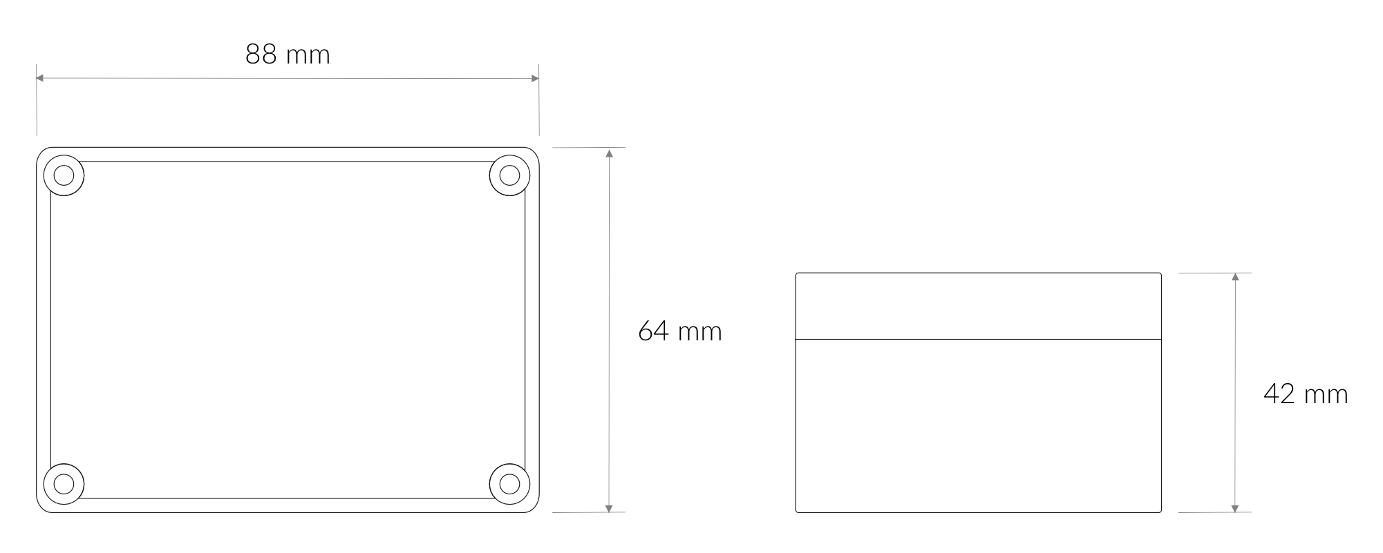
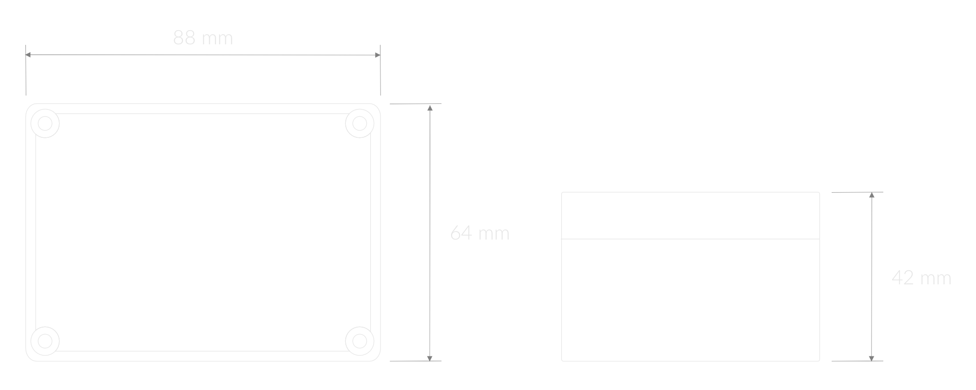
Figure 3. Dimensions of the device
Device
| Attribute | Description |
|---|---|
| Dimensions | Height: 42 mm Width: 88 mm Depth: 64 mm |
| Colour | Light Grey |
| Mounting method | Horizontal Vertical (can be screwed to the wall) |
| Enclosure material | ABS |
| Level of protection | IP67, IK09 |
| Weight (without batteries, excl. probes) | 134 g |
Pitot Tubes
Use the Pitot Tube Selector to find the right insertion length for a circular or rectangular duct.
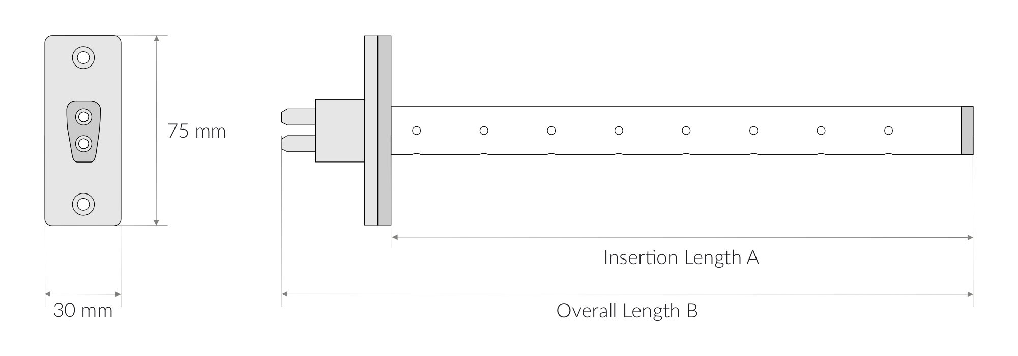
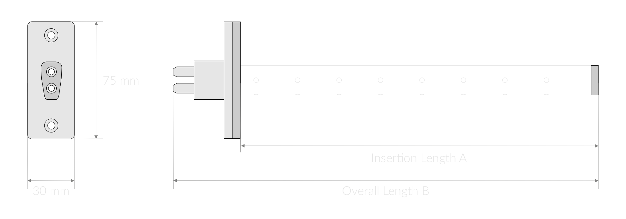
Figure 4. Pitot Tubes
| Attribute | Description |
|---|---|
| Base Dimensions | 30 mm x 75 mm |
| Insertion Lengths (A) | 150 mm, 200 mm, 250 mm, 300 mm, 350 mm, 400 mm, 450 mm, 500 mm, [custom length] |
| Overall Lengths (B) | 193 mm, 243 mm, 293 mm, 343 mm, 393 mm, 443 mm, 493 mm, 543 mm |
| Colour | Blue |
| Tubes length | 1 m |
| Mounting method | Mounting plate, screws |
| Materials | Aluminium alloy, Rubber, ABS, PU |
| Weights | 160 g, 175 g, 185 g, 200 g, 210 g, 225 g, 235 g, 250 g |
Silicon Tubes
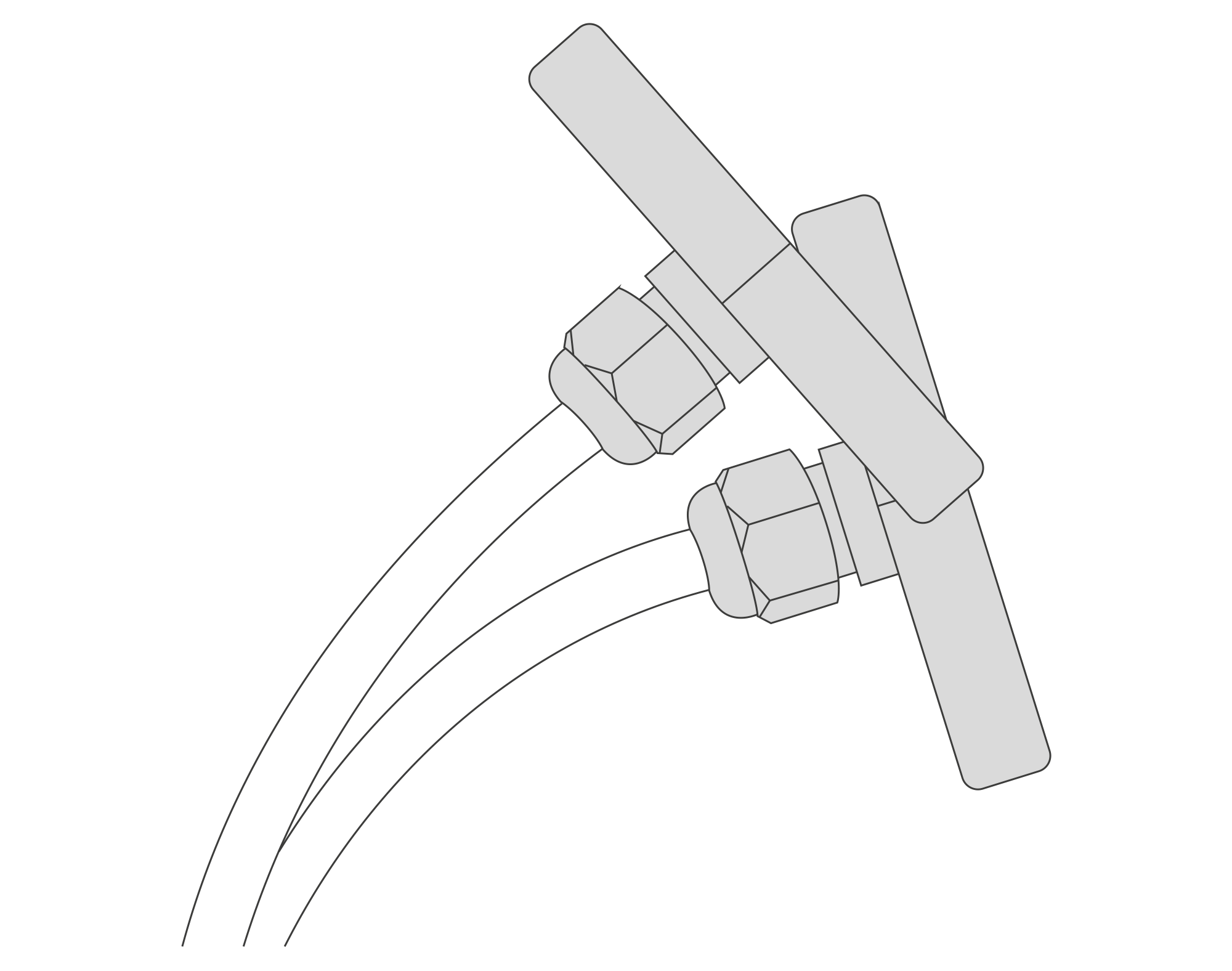
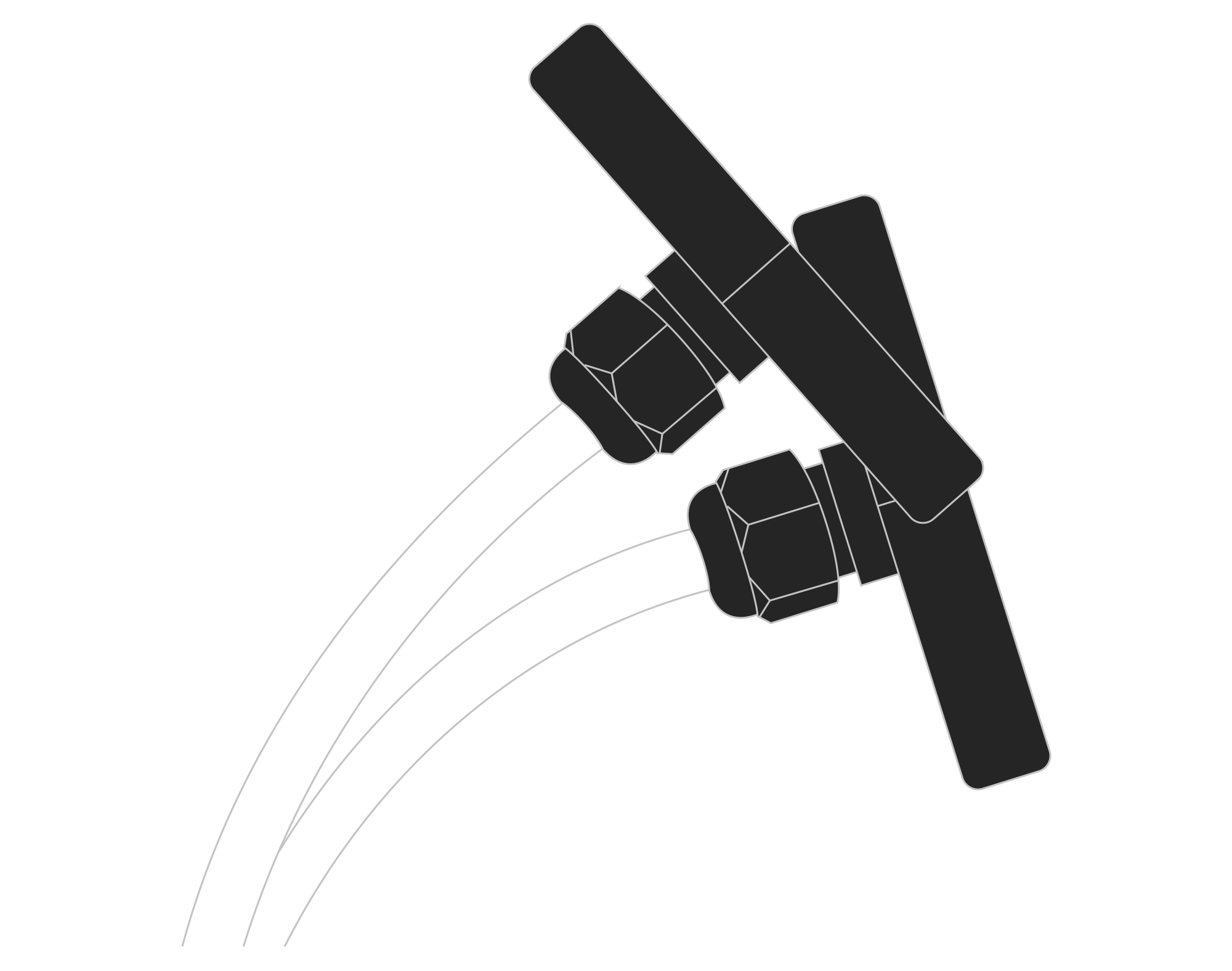
Figure 5. Silicon Tubes
| Attribute | Description |
|---|---|
| Base Dimensions | 83.5 mm x 40 mm |
| Colour | Dark Grey / Transparent |
| Tubes length | 2 m |
| Materials | PETG, PU |
| Weight | 115 g |
Operating Conditions
| Attribute | Description |
|---|---|
| Temperature | 0°C to 70°C |
| Humidity | 0 to 90% |
| Placement | Indoor use |
| Power supply | 3 x LR6 (AA) battery (3 x 1.5 V) |
| Power consumption | Maximum: 120 mA DC (4.5 V DC) |
Measured Values
| Parameter | Measurement range | Accuracy |
|---|---|---|
| Temperature (internal) | -40°C to 125°C | ±0.2°C (5°C to 60°C) |
| Relative humidity (internal) | 0% to 100% | ±2% (20% to 80%) |
| Differential pressure | -500 Pa to 500 Pa | 0.1 Pa + 3% reading (temperature dependent) |
| Velocity (Pitot tube required) | 0 m/s to 24.68 m/s | ±2% (temperature dependent) |
Controls and Indicators
LED Status Indicator
YO Airflow Pro communicates its current behaviour to the user by RGBW LED placed on the top.
Diode statuses interpretation
| Behavior | Colour | Status |
|---|---|---|
| Single flash | Green | General: device is working correctly (power and memory). |
| Single flash | Red | General: device is working incorrectly (power and memory). LoRaWAN communication: failed to receive an acknowledgement from LoRaWAN Server within specified timeout. |
| Single flash | White | LoRaWAN communication: LoRaWAN frame sent / confirmation from LoRaWAN Server after receiving the frame. |
| Slow flashing | Blue | BLE communication: connection to the device via BLE (configuration). |
| Rapid flashing | Blue | LoRaWAN communication: connecting to LoRaWAN network. |
Buttons
The YO Airflow Pro has a button for resetting the device. Figure 6 shows its placement. To reboot the device, press the reset button for a moment.
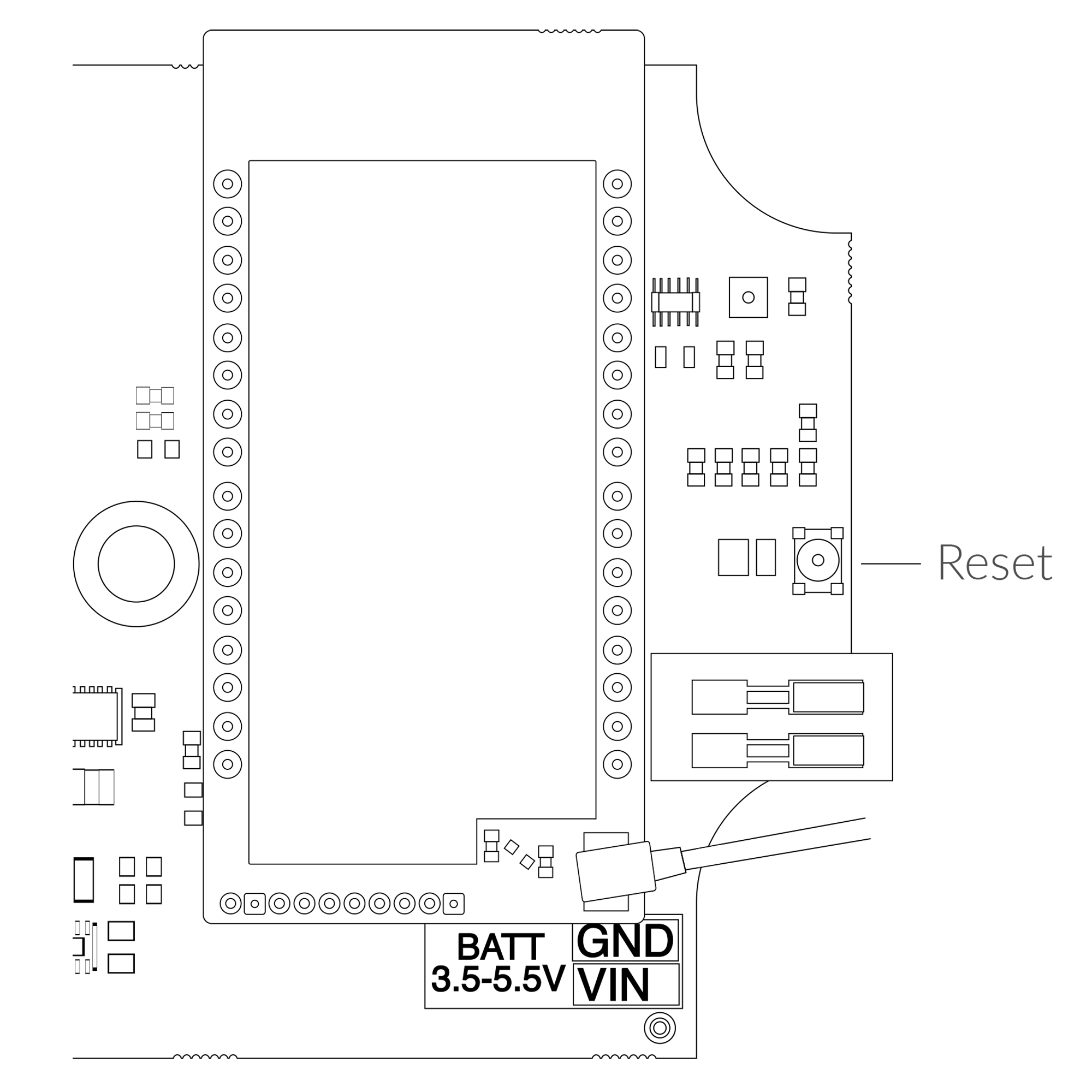
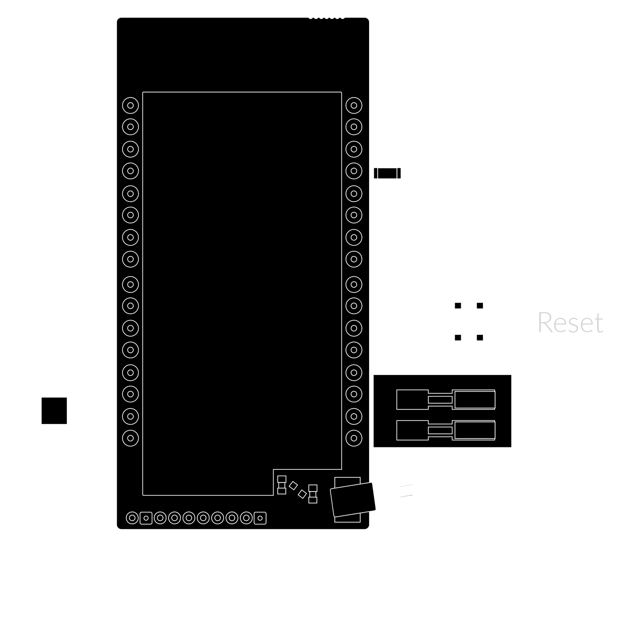
Figure 6. Reset button
Installation
Package Contents
- Device (without batteries).
- Silicon tubes
- Brackets or pitot tubes (sold separately)
- Warranty card.
Safety Precautions
Go to the Safety Precautions section to see important information on handling, disposal and maintenance.
Installation Guide
- Unscrew the device: remove 4 screws from the enclosure.
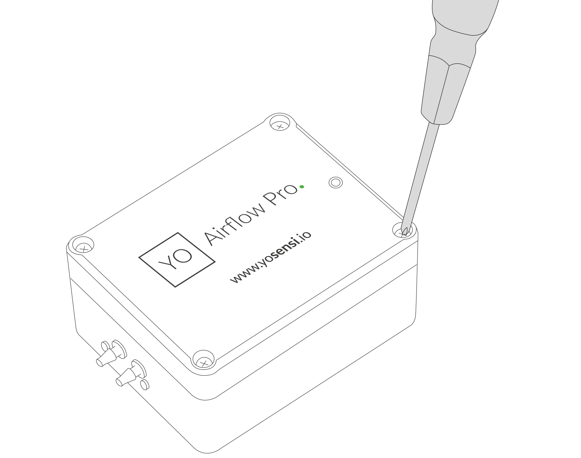
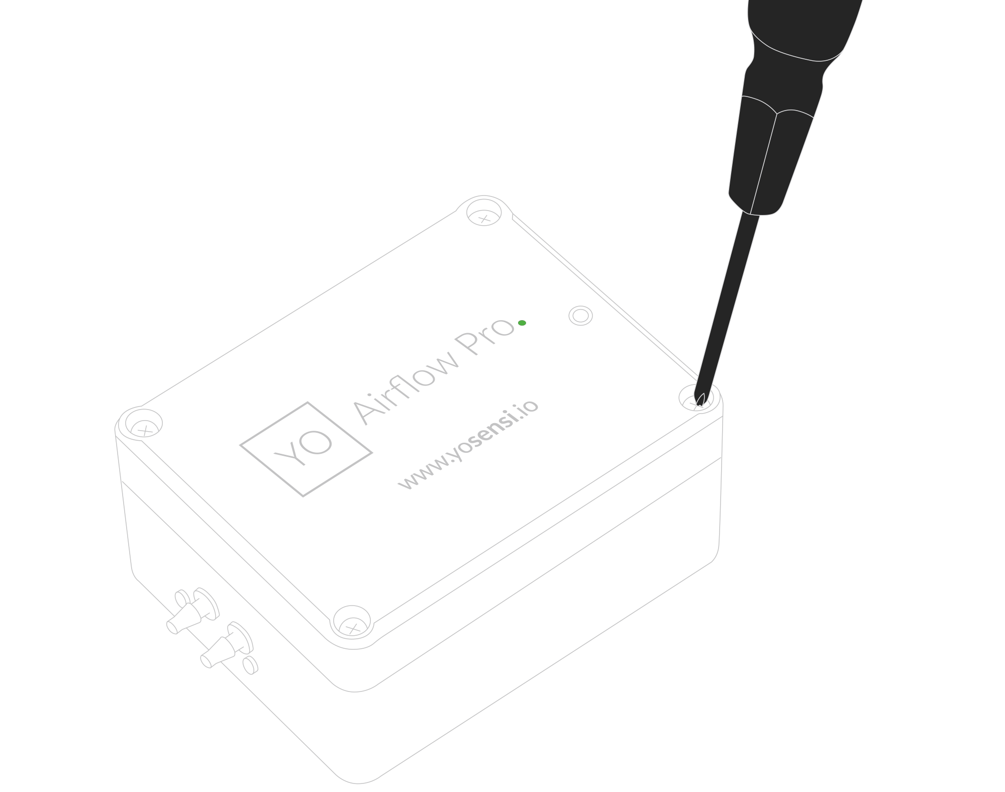
Figure 7. Device opening instructions
- Place three LR6 batteries in the device according to the polarity indicated on the battery holder.
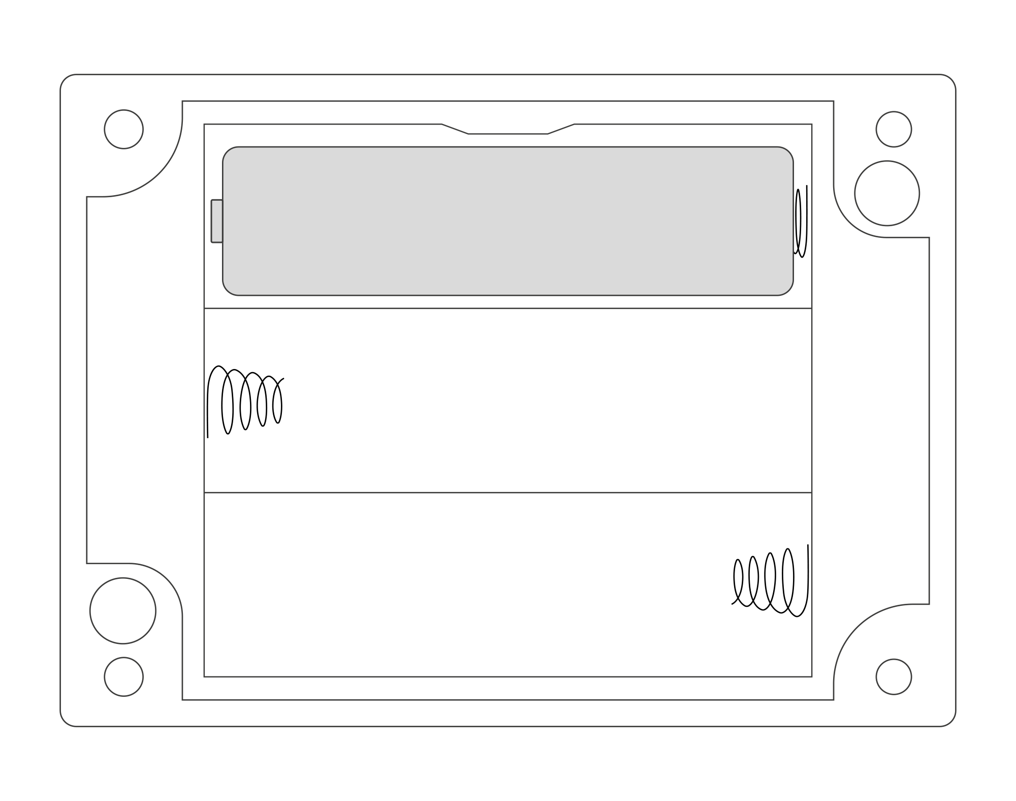
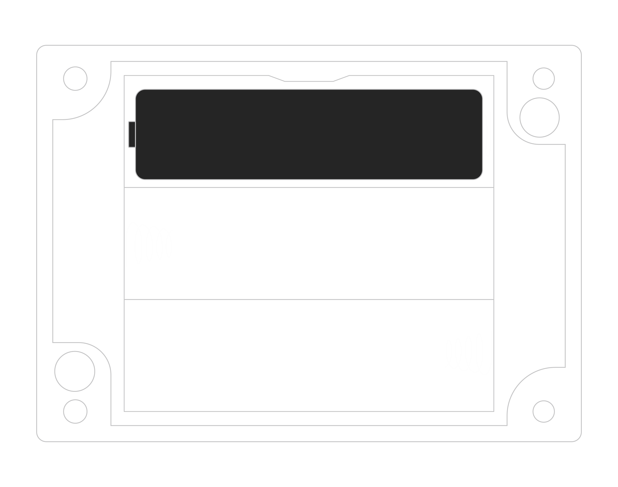
Figure 8. Battery placement instructions
-
The device is on. Screw it back together.
-
Insert the silicone tubing onto the sensor inputs.
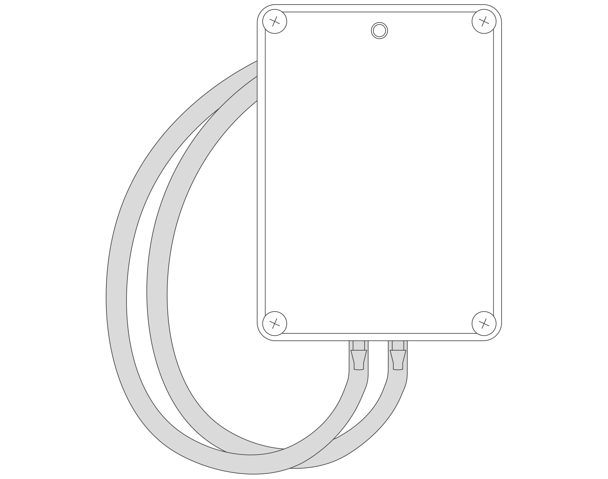
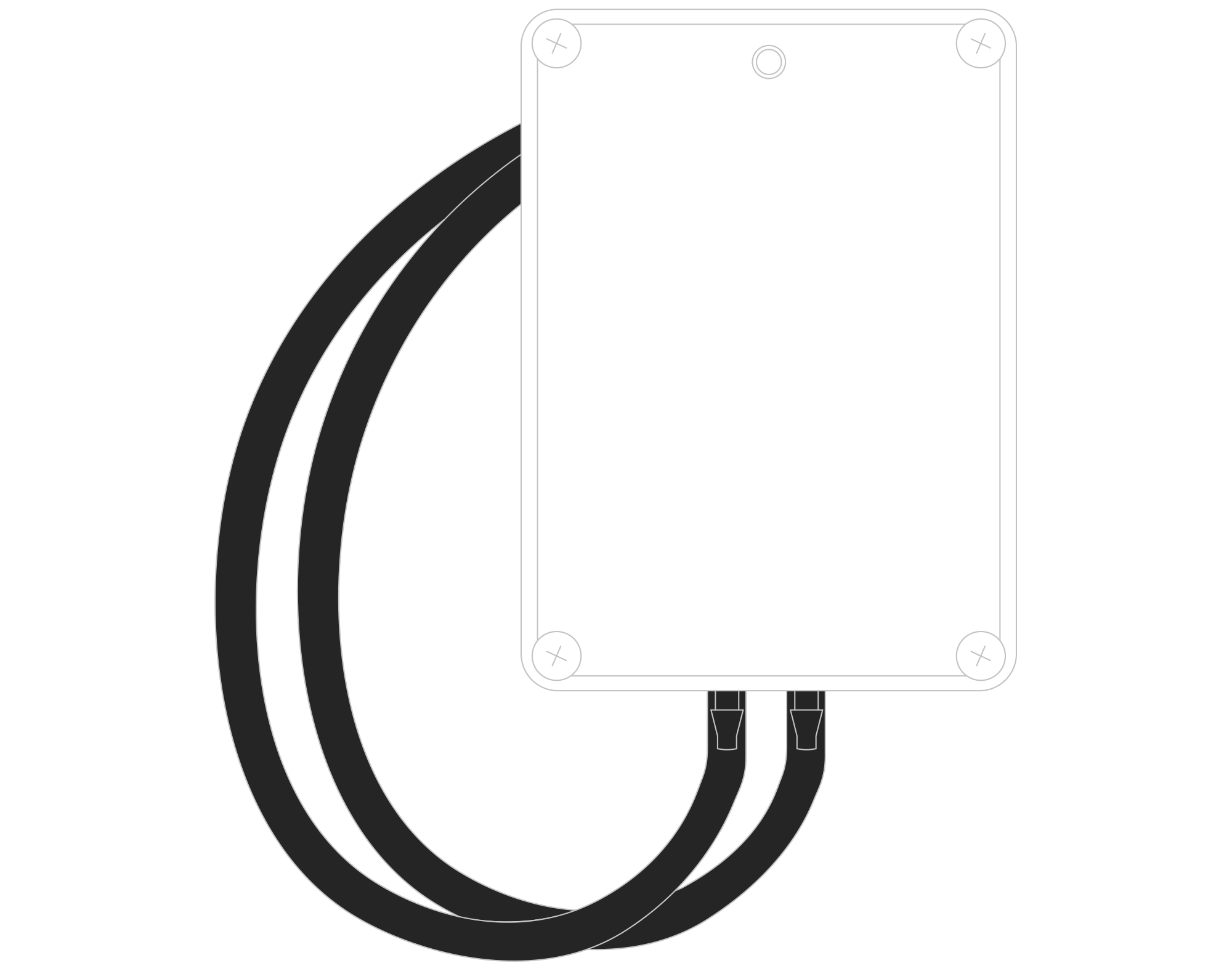
Figure 9. Connecting silicone tubing instructions
Important! The sensors must be placed according to the following diagram, i.e. the sensor measuring the higher pressure must be placed on the right side and the one measuring the lower pressure on the left side:
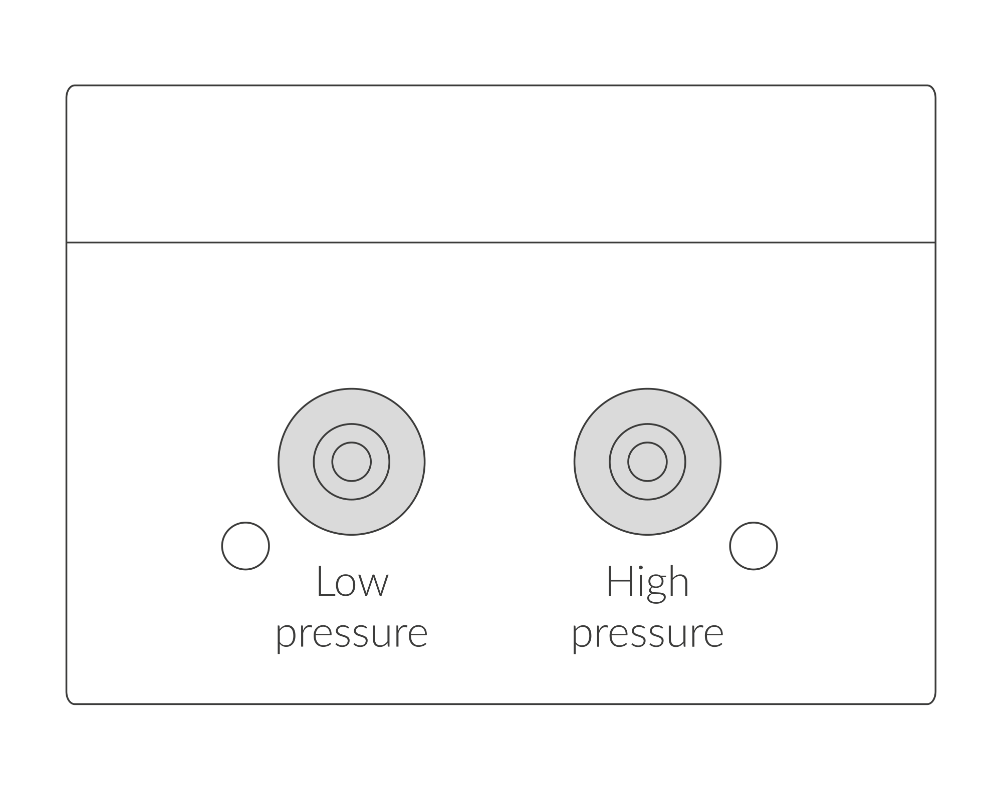
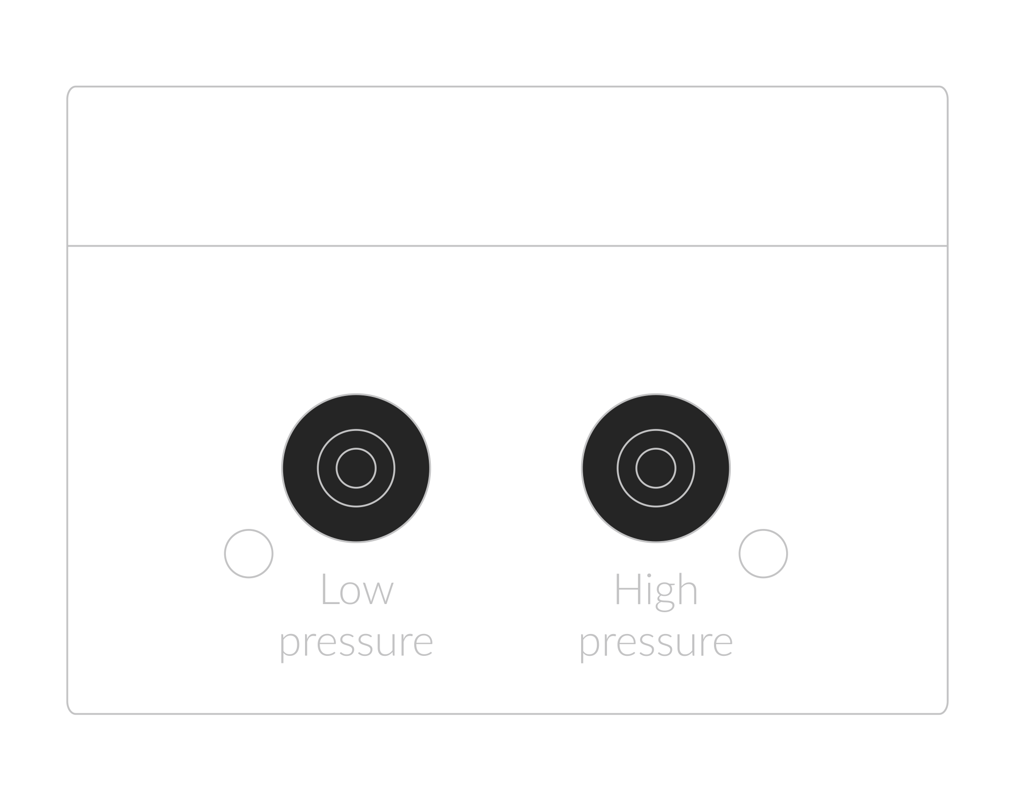
Figure 10. Connecting silicone tubing side view instructions
Important to avoid breaking the device! In case of removing silicone tubes it is necessary to cut off the tubes from the connectors i.e. with a sharp knife. First tubes must be cut off on the edge of the sensor with high or low pressure, then cut off the rest of the silicon tube located along the black sensor. Then take off the rest of the silicon tube gently without breaking the sensor.
- Place the brackets in accordance with their use:
- The sensor measuring the higher pressure must be placed where the higher pressure occurs.
- The sensor measuring the lower pressure must be placed where the pressure is lower.
Figure 11. Connecting silicone tubing with brackets instructions
- In case of Pitot Tube usage for velocity measurement:
- Connect the two pressure tubes from the sensor to the Pitot tube: slide the tube measuring total pressure onto the "high" connector, and the tube measuring static pressure onto the "low" connector of the Pitot tube.
- Drill a 1-7/8” hole in the center of the duct or pipe where the sensor is to be installed.
- Drill a 1/2” hole on the opposite side for double support.
- Attach the opposite end-guide rod through both holes, ensure the correct flow direction, and secure the mounting plate to the duct or pipe using self-tapping screws.
- The direction of the airflow is marked on the pitot tube at the connections of the air tubes to the node.
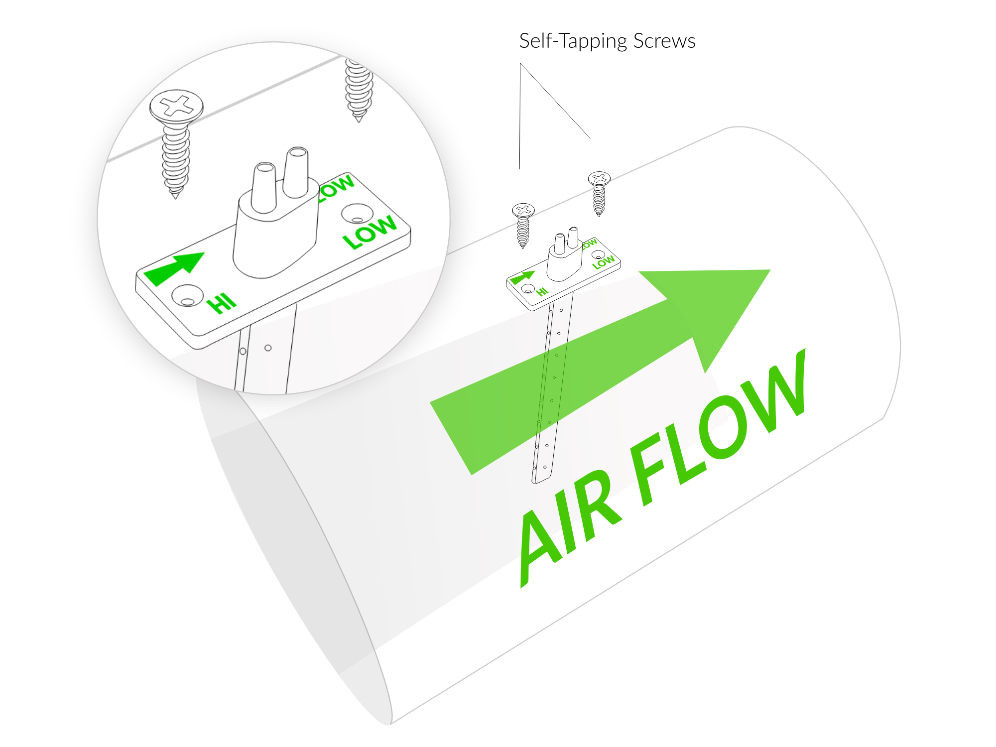
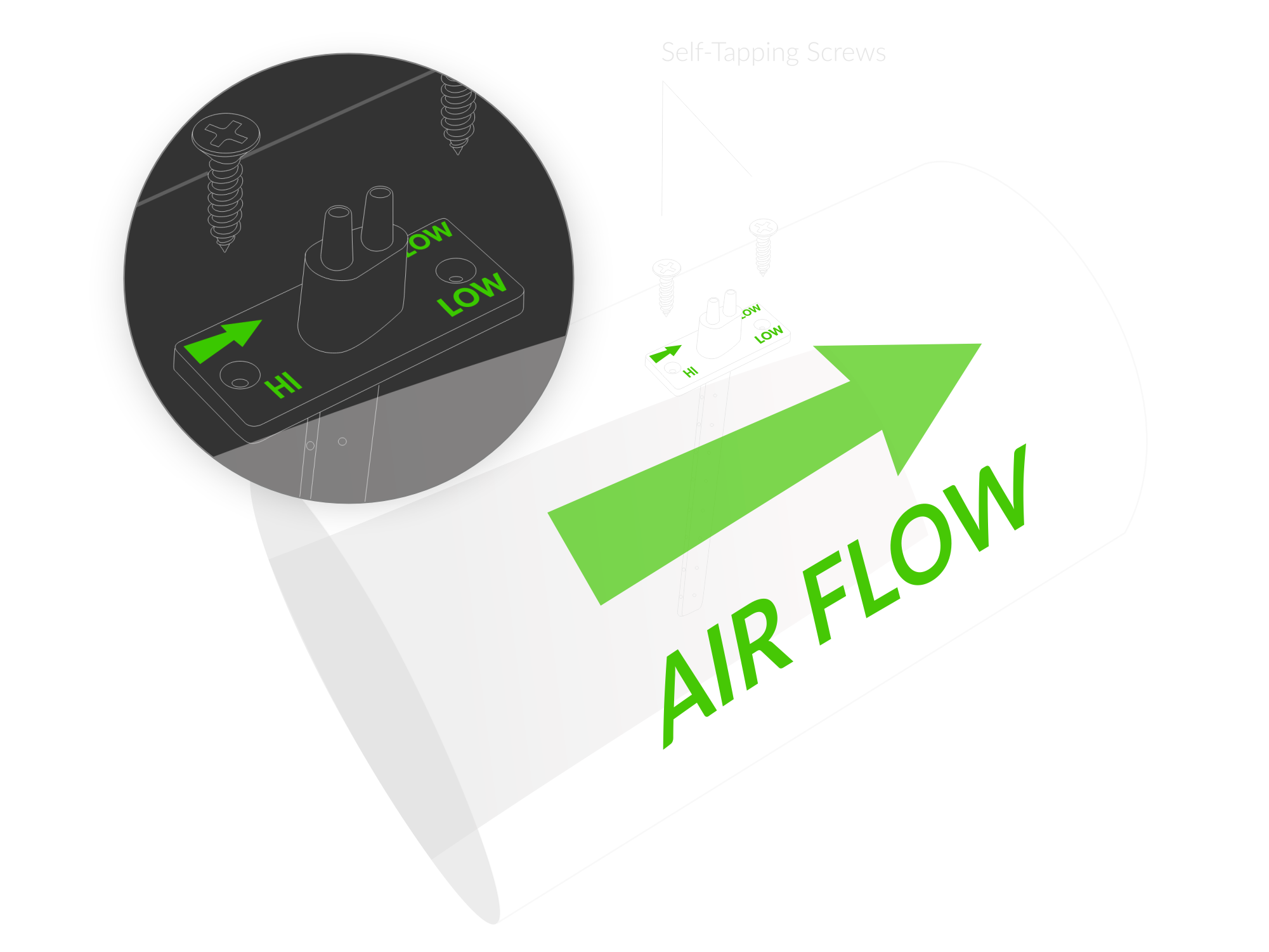
Figure 12. Mounting pitot tube instructions
Configuration
Configurable Parameters
A few parameters must be set before sending data to the gateway. The default firmware is configured in OTAA mode with predefined deveui, appkey (OTAA) and appskey, nwkskey (ABP).
Configuration of the device is stored in a JSON file divided into the following sections:
- info (generic, read only): information about the device,
- general (generic): general device settings,
- lorawan (generic): configuration data for LoRaWAN connection,
- ble (generic): Bluetooth settings,
- device (dynamic): individual configuration for a specific device (this section’s structure differs for each device),
Sample configuration file for the YO Airflow Pro device.
{
	"info": {
		"devmodel": "LNAP",
		"fwver": "3.6.9",
		"loraradio": "SX1261",
		"lorawanver": "1.0.2",
		"loraregion": "EU868",
		"blemacaddr": "0123456789ab"
	},
	"general": {
		"rtcstate": "disable"
	},
	"lorawan": {
		"subband": 1,
		"retrycnt": 3,
		"nwktype": "private",
		"acttype": "abp",
		"otaa": {
			"deveui": "0123456789abcdef",
			"appeui": "fedcba9876543210",
			"appkey": "000102030405060708090a0b0c0d0e0f",
			"trials": 3
		},
		"abp": {
			"devaddr": "01234567",
			"nwkskey": "0123456789abcdef0123456789abcdef",
			"appskey": "000102030405060708090a0b0c0d0e0f"
	}
	},
	"ble": {
		"power": 0,
		"interval": 1600
	},
	"device": {
		"velocity": {
			"kfactor": 0.855,
			"altitude": 0,
			"calculatevelocity": "disable"
    	},
		"measinterval": 3600
	}
}
OTAA & ABP
| OTAA | ABP |
|---|---|
| Device EUI | Device Address |
| Application EUI | Network Session Key |
| Application Key | Application Session Key |
| Number of Trials |
Generic Parameters
Click here to see the generic parameters for Yosensi devices.
Parameters
Device Parameters
| Name | Description | Possible Values | Default Value | Read/Write |
|---|---|---|---|---|
| measinterval | Measuring and sending interval LoRa [s] | 601-999999 | 3600 | R/W |
| kfactor | Calibration constant for the specific Pitot tube design | 0.8-1.2 | 0.855 | R/W |
| altitude | Altitude correction for accurate velocity calculation (air density) [m] | 0-2000 | 0 | R/W |
| calculatevelocity | Enables velocity measurement in data uplink | disable enable | disable | R/W |
| ||||
Parameters description
- rtcstate: used for enabling/disabling the real-time clock (RTC) inside the device. The RTC is used for timestamping the measurements.
- nwktype: used for setting the device in public or private network type.
- acttype: used for setting the device in ABP or OTAA mode.
- deveui, … , appskey: predefined addresses and keys, these parameters are generated using multiple IDs specific to the particular MCU and are unique for each device. They can be changed if needed.
- interval: determines the interval of sending broadcast packets, used to connect to every BLE receiver around the device.
- subband: used for setting the communication frequency sub-band in LoRaWAN.
- retrycnt: number of retries to send a LoRa packet if the acknowledgement is not received from the LoRaWAN server.
- measinterval: measurement interval [s] between sending LoRa packets.
- kfactor: A correction factor that compensates for installation discrepancies in variable air volume terminal units to ensure accurate airflow measurement and control.
- altitude: Altitude correction is necessary for accurate velocity calculations using Pitot tubes at different elevations. It adjusts for the lower air density at higher altitudes, ensuring precise airflow measurements in HVAC applications.
- calculatevelocity: disable or enable velocity measurement. When enabled, measurement is added to the uplink data.
Downlink message
You can remotely adjust certain parameters by sending a downlink message through our platform. Simply navigate to the "COMMANDS" section for the selected device.
Change Measurement Interval
It is possible to change the measurement interval (measinterval) by using downlink. Information about changing the parameter will be sent from the server via the gateway.
Example of Downlink Message:
- Prefix:
0x03 - Measurement Index:
0x00 - Data (up to 4 bytes in hex):
0258
Sample Downlink: 0x03000258 - Sets a measurement interval of 600 seconds (10 minutes).
Click here to see how to connect a node using the Yosensi Management Platform.
See how to configure a node in Yosensi Management Platform
Check how to adopt and configure a node via the Yosensi App.
Take a look at the list of frequency plans used in Yosensi.
This datasheet describes the payload protocol developed by Yosensi for communicating with our devices.
Payload Decoder
If you want to connect to your own server, it is necessary to decode the specific payload for each device. To accomplish this, a payload decoder is required, which can be downloaded using the following link: Payload decoder. You can also use our integrated Payload Decoder here. Extended documentation of the protocol can be found in the Payload description on our website.
Compliance Statements
To view or download the Declaration of Conformity for YO Airflow Pro go here