YO Modbus
Overview
Description
The YO Modbus acts as a bridge between the Modbus network and LoRaWAN, enabling users to read data from Modbus RTU slave devices and send it via LoRaWAN. It supports up to 150 Modbus queries, transmitting them in a maximum of 30 LoRa packets, with each packet capable of carrying up to 5 queries. This efficient data transfer capability ensures seamless integration between Modbus devices and LoRaWAN networks.
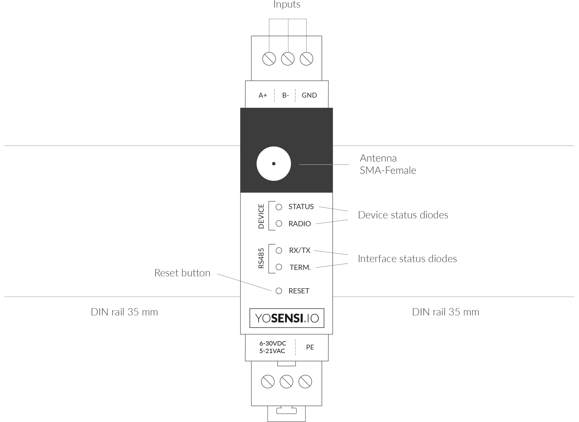
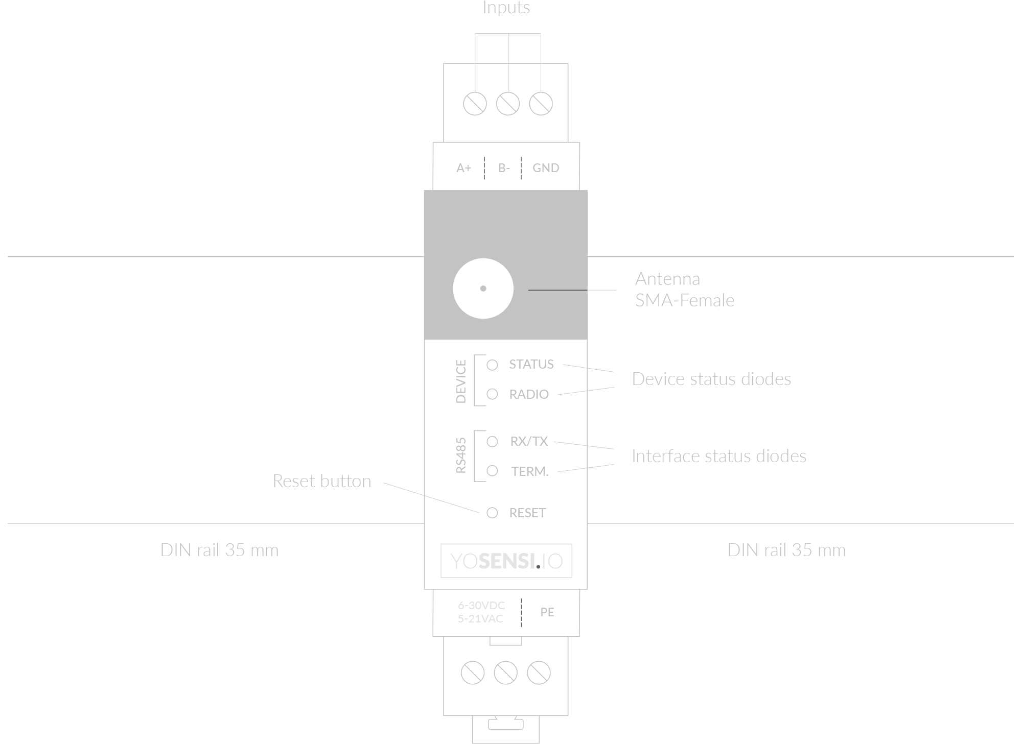
Figure 1. Device top view
Device sticker placed on the right side of the device enclosure contains information about model, version, LoRaWAN region and 3 parameters important in case of device identification and configuration:
- DEV EUI: 64-bit unique device identifier in a LoRaWAN network,
- DEV ADDR: address required to connect via ABP activation type to LoRaWAN,
- BLE MAC: Bluetooth physical address.

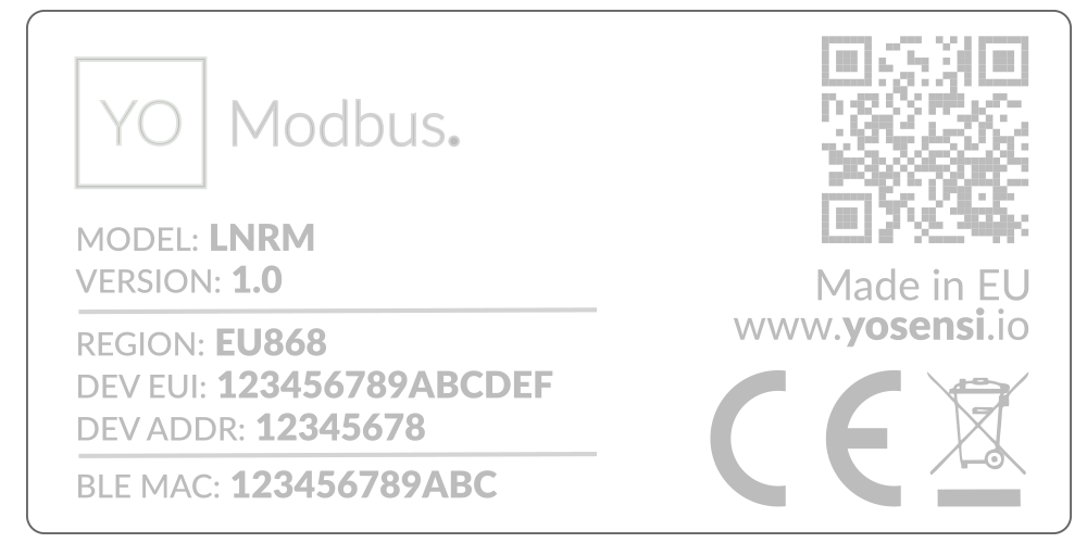
Figure 2. Device sticker
Features
- LoRaWAN Technology: Available in multiple versions with LoRa radio configured for various regions and ISM frequency bands (e.g., EU868, US915, AU915), it is compatible with both private and public LoRaWAN networks and supports connections via ABP (Activation by Personalization) or OTAA (Over-The-Air Activation).
- Bluetooth Low Energy (BLE): Enables easy configuration through a user-friendly JSON data exchange format, supports firmware updates via OTA (Over-the-Air), and boasts very low energy consumption.
- Modbus Network: Can request up to 150 different queries from slave devices.
- RS485 input: Galvanically isolated from the rest of the device modules for maximum protection.
- Yosensi Management Platform: Provides a web tool for device configuration, firmware updates, and infrastructure management. Enables comprehensive monitoring of transmitted data and easy device management.
- Yosensi Mobile App: Effortlessly manage devices with features to register new ones, configure settings, perform firmware updates, view/send logs, and test LoRaWAN connectivity. Learn more in our detailed Yosensi App blog post.
Specifications
Physical
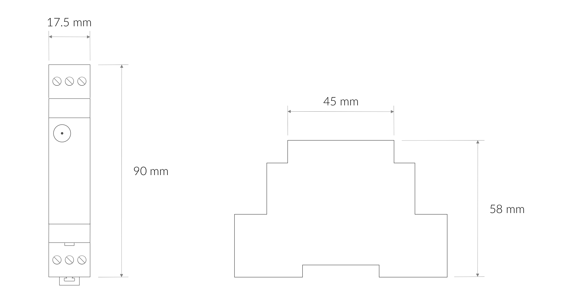
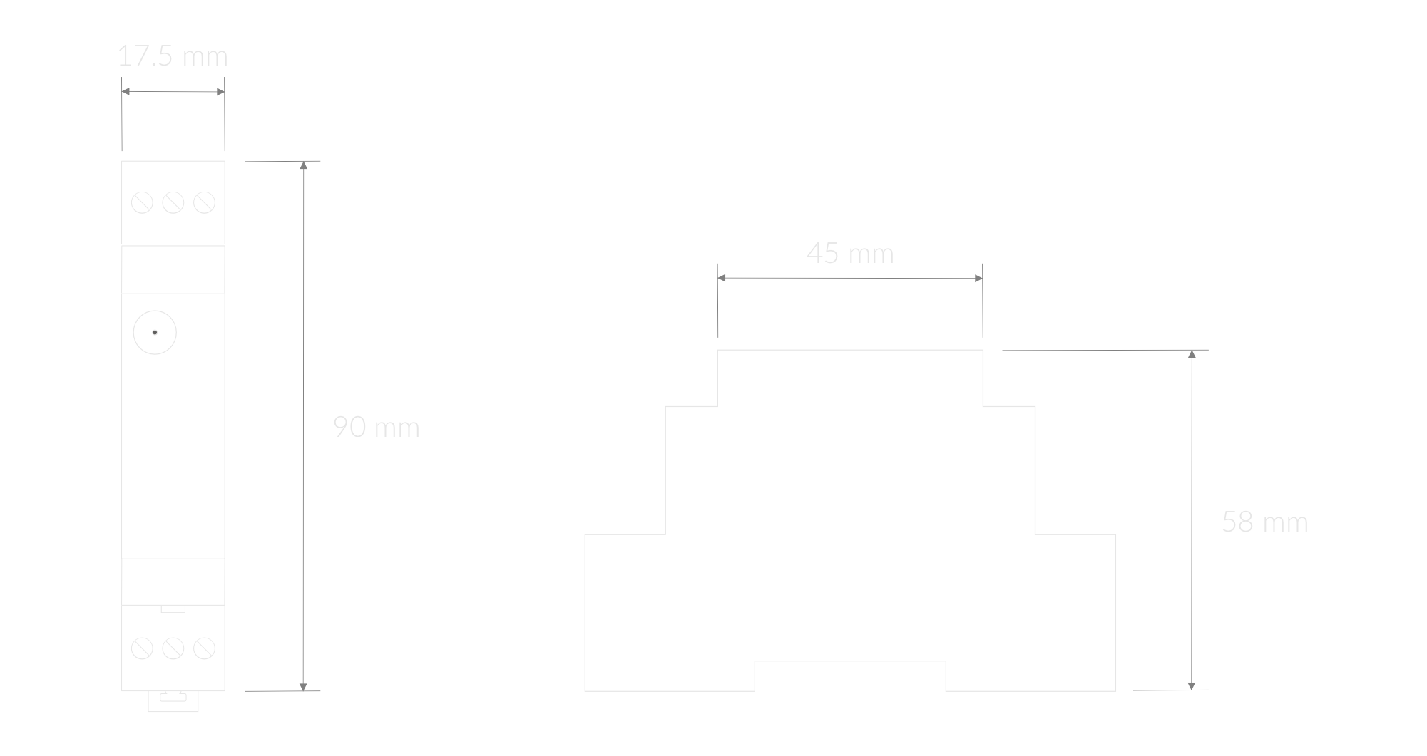
Figure 3. Dimensions of the device
Device
| Attribute | Description |
|---|---|
| Dimensions | Height: 90 mm Width: 17.5 mm (1 pole) Depth: 58 mm |
| Colour | Light Grey |
| Mounting method | 35 mm DIN rail standard |
| Enclosure material | Polycarbonate |
| Level of protection | IP20, UL94-VO |
| Input signal | Digital RS485 |
| Weight | 90 g |
Operating Conditions
| Attribute | Description |
|---|---|
| Temperature | 0°C to 70°C |
| Humidity | 0 to 90% |
| Placement | Indoor use |
| Power supply | 6-30 V DC 5-21 V AC |
| Power consumption | Typical: 12 mA DC (12 V DC) Maximum: 120 mA DC (12 V DC) |
Measured Values
| Parameter | Measurement range | Accuracy |
|---|---|---|
| Internal Voltage | 6-30 V DC | - |
| Queries and Polls | - | - |
Queries and polls
YO Modbus can request up to 150 different queries from slave devices. Establishing communication requires advance knowledge of the device's starting registers, slave address and function codes. This device supports the following read functions:
- 01 (0x01) Read coils
- 02 (0x02) Read discrete inputs
- 03 (0x03) Read holding registers
- 04 (0x04) Read input registers
- 05 (0x05) Write single coil
- 06 (0x06) Write single holding register
- 0F (0x0F) Write multiple coils
- 10 (0x10) Write multiple holding registers
The query data are read by Modbus RTU and sent by LoRaWAN. Each LoRa packet contains data from the read registers. One LoRa packet can contain 5 user-created polls, each up to 4 bytes.
More information can be found in the parameters section.
RS485 Interface
Connecting RS485 Nodes to YO Modbus
- Connect the A+ line to the RS485 A bus and B− line to the RS485 B bus.
- Connect GND to the ground terminal of the RS485 bus.
Power Supply
- The device supports 6–30 VDC or 5–21 VAC power input.
- Optionally, connect a protective earth cable. To avoid loop currents, ensure the earth connection is made at only one point in the network.
Line Topology and Termination
- For certain line topologies, terminating loads may be required depending on the cable length.
- The termination load impedance should match the line impedance on both ends, typically 120 Ω on each side.
- The device includes a built-in terminating resistor (RT).
Communication
YO Modbus operates by:
- Sending queries to each device in the network.
- Converting the collected data into LoRa frames for relay to the application server.
Before communication begins:
- Configure the serial transmission settings in the YO Modbus device.
- Obtain the slave addresses and the individual registers required for reading data.
Controls and Indicators
LED Status Indicator
YO Modbus communicates its current behaviour to the user by RGBW LED placed on the top.
Diode statuses interpretation
| Behavior | Colour | Status |
|---|---|---|
| Single flash | Green | General: device is working correctly (power and memory). |
| Single flash | Red | General: device is working incorrectly (power and memory). LoRaWAN communication: failed to receive an acknowledgement from LoRaWAN Server within specified timeout. |
| Single flash | White | LoRaWAN communication: LoRaWAN frame sent / confirmation from LoRaWAN Server after receiving the frame. |
| Slow flashing | Blue | BLE communication: connection to the device via BLE (configuration). |
| Rapid flashing | Blue | LoRaWAN communication: connecting to LoRaWAN network. |
| Continuous lit | Orange | Term diode: Terminating resistor connected. |
| Rapid flashing RS485 | Red | RX/TX diode: RS485 packet sent. |
| Green | RX/TX diode: RS485 packet received. |
Buttons
YO Modbus is equipped with one reset button under the interference status diode RX/TX shown on the device top view. It is possible to press it with a thin pin.
Figure 4. Device reset button
Installation
Package Contents
- Device.
- Antenna.
- Warranty card.
Safety Precautions
Go to the Safety Precautions section to see important information on handling, disposal and maintenance.
Installation Guide
- Mount the device on a 35 mm DIN rail.
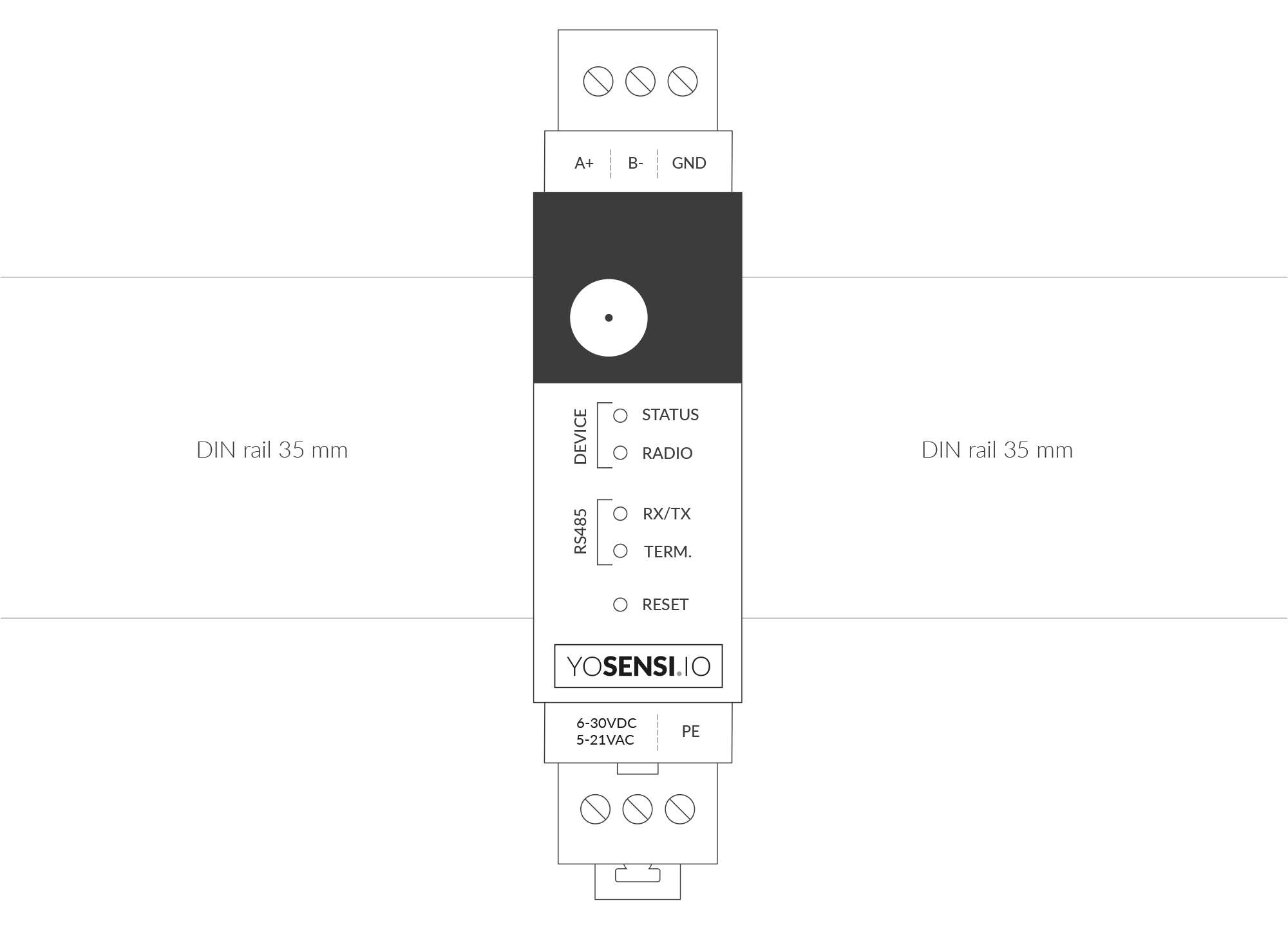
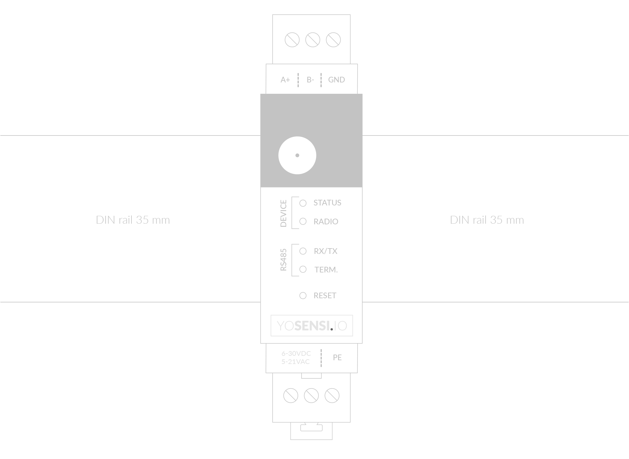
Figure 5. Device mounted on 35 mm DIN rail
- Screw RS485 protocol communication wires to the device's A+ and B- terminal blocks. Optionally, connect cable shielding to the device's GND terminal block.
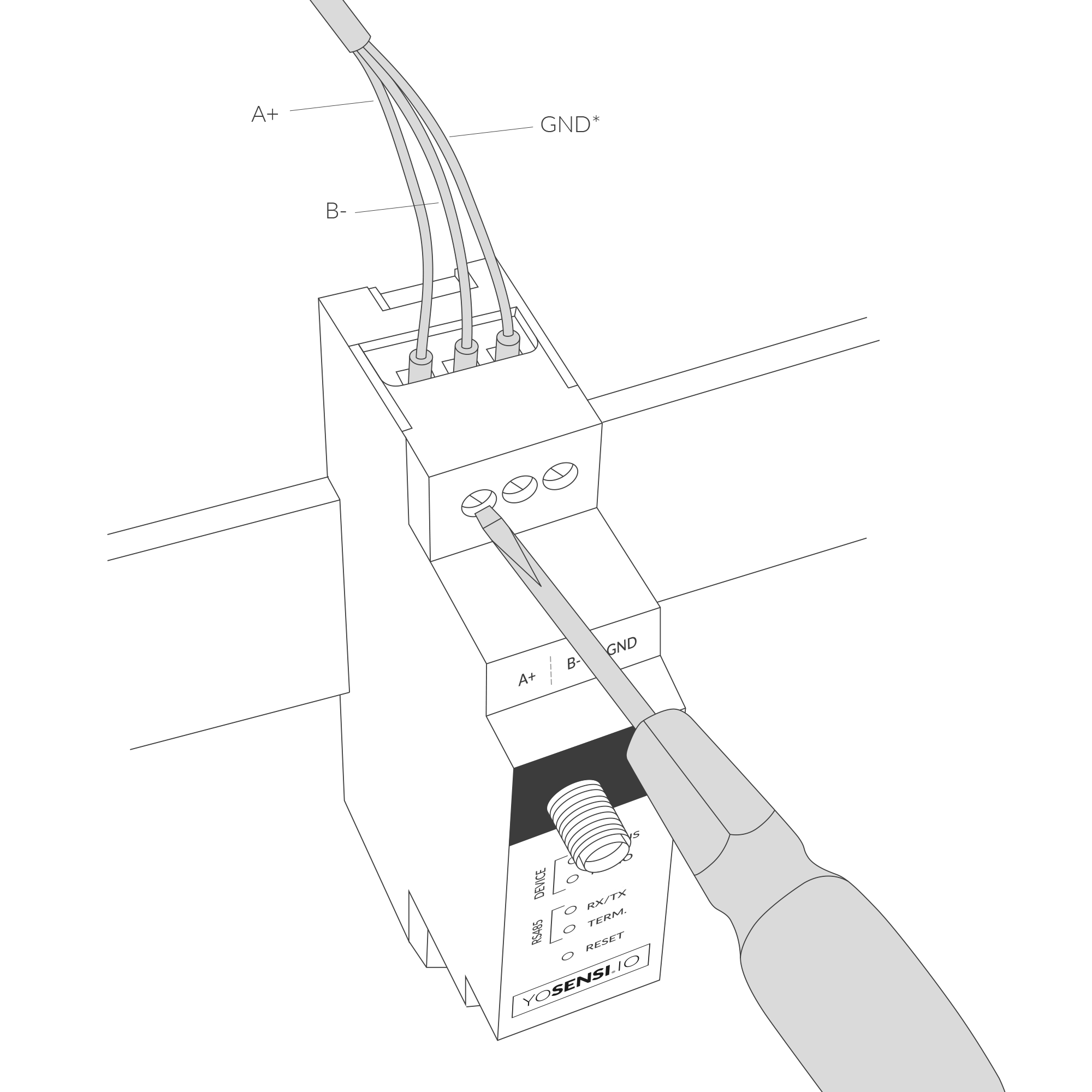
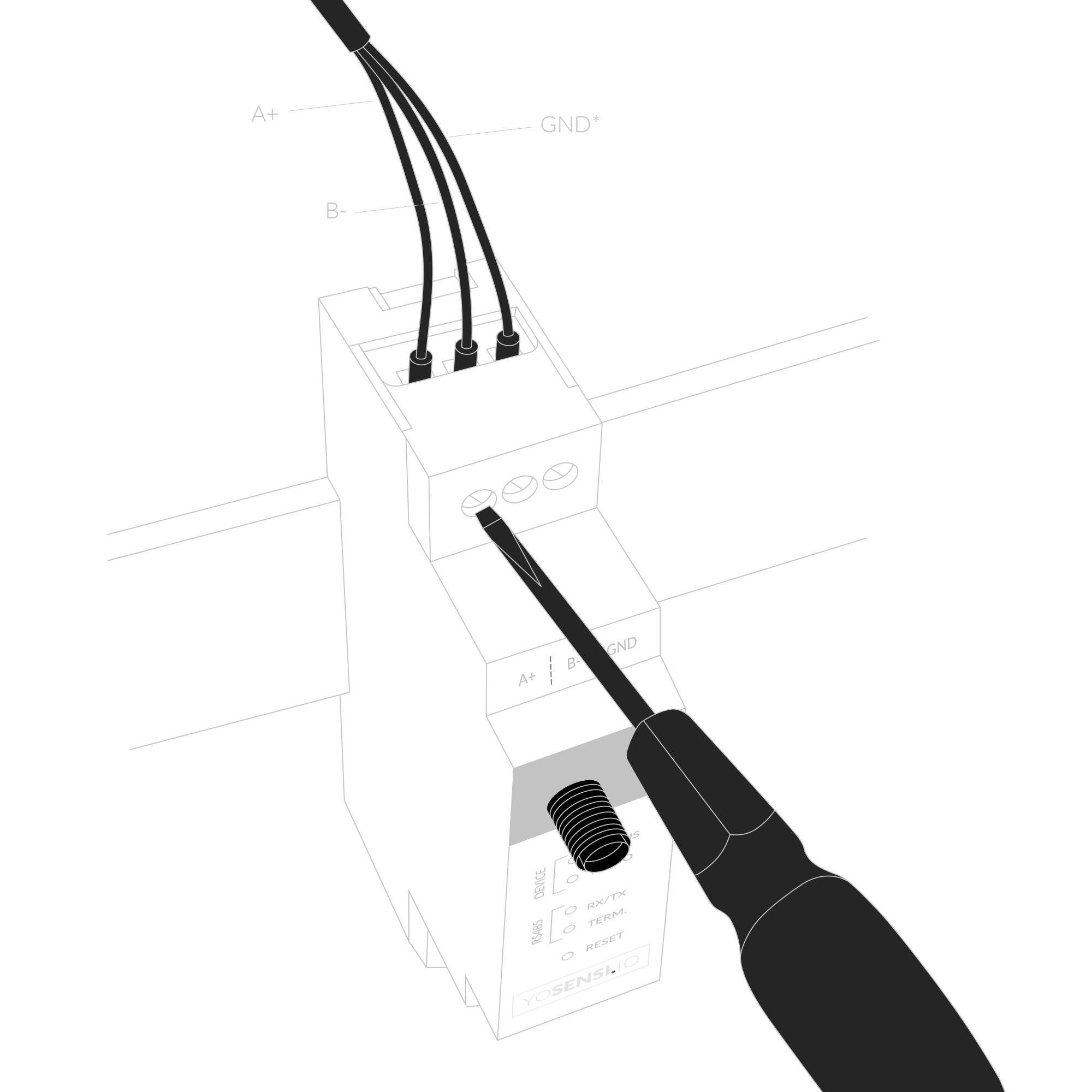
Figure 6. Connecting communication wires to device terminal blocks
- Screw the power supply wires to the device (6-30 V DC, 5-21 V AC). Optionally, connect a protective earth (PE) cable. Once power is connected, the indicator diodes should behave as described in LED Status Indicator.
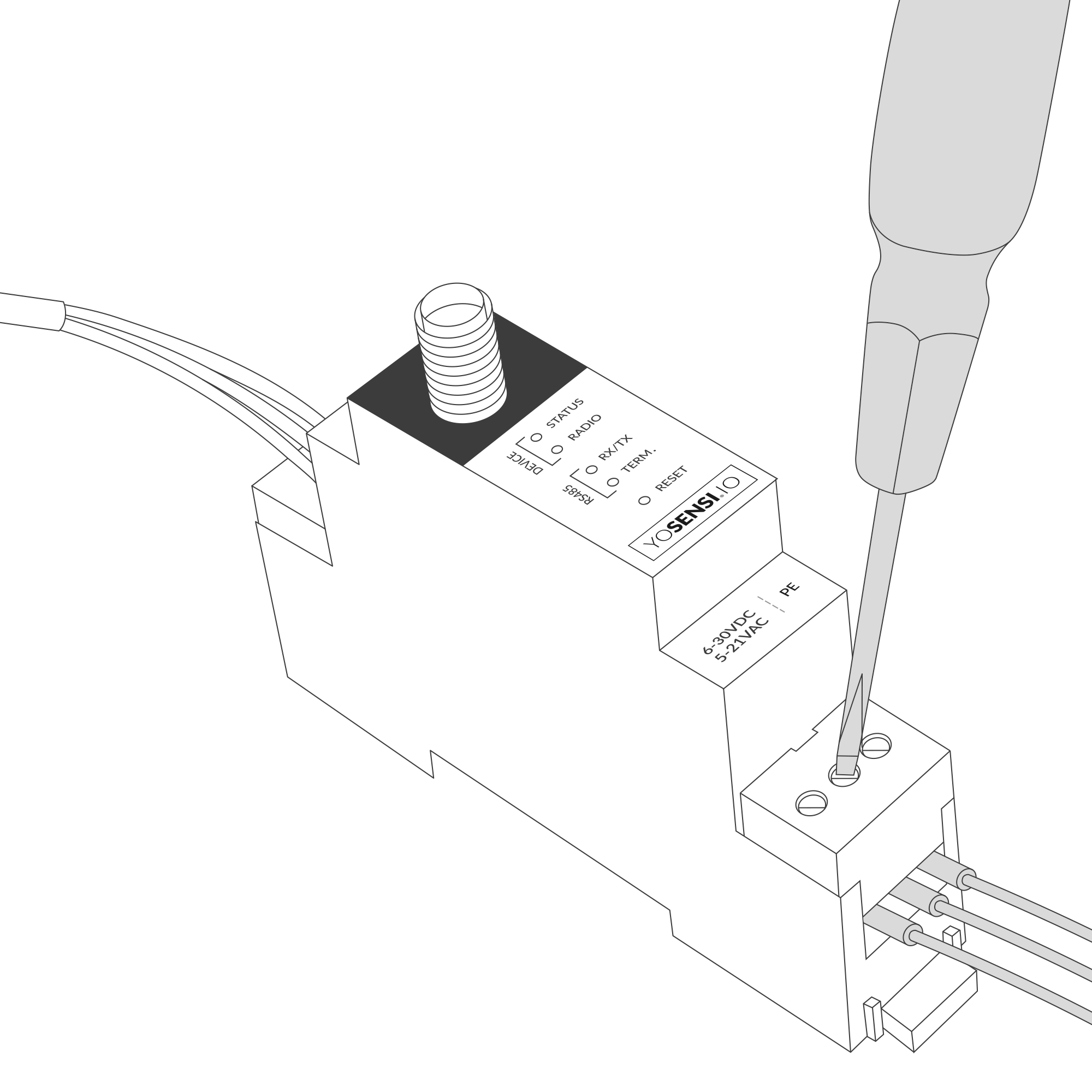
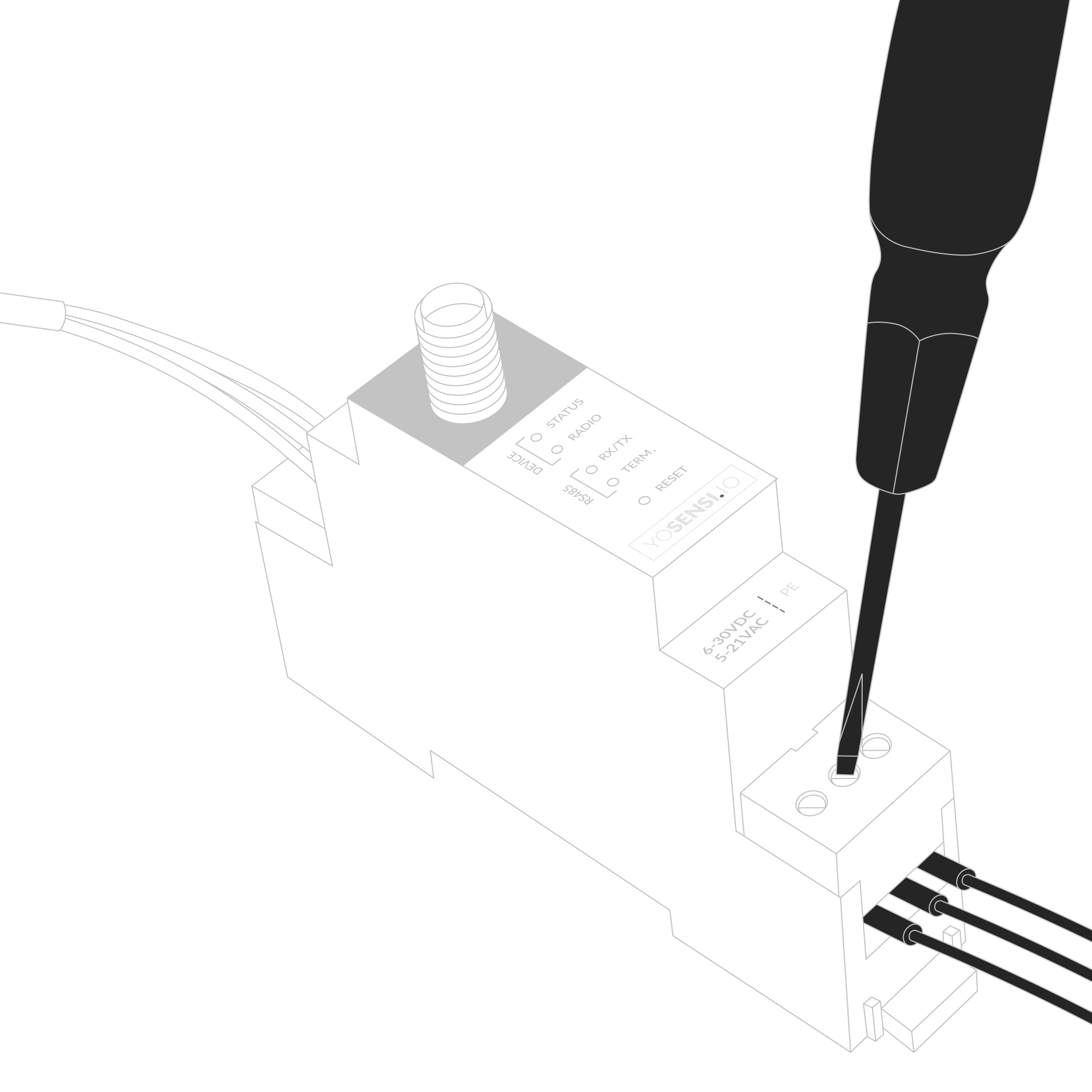
Figure 7. Connecting power supply to the device
- Connect the antenna to the device.
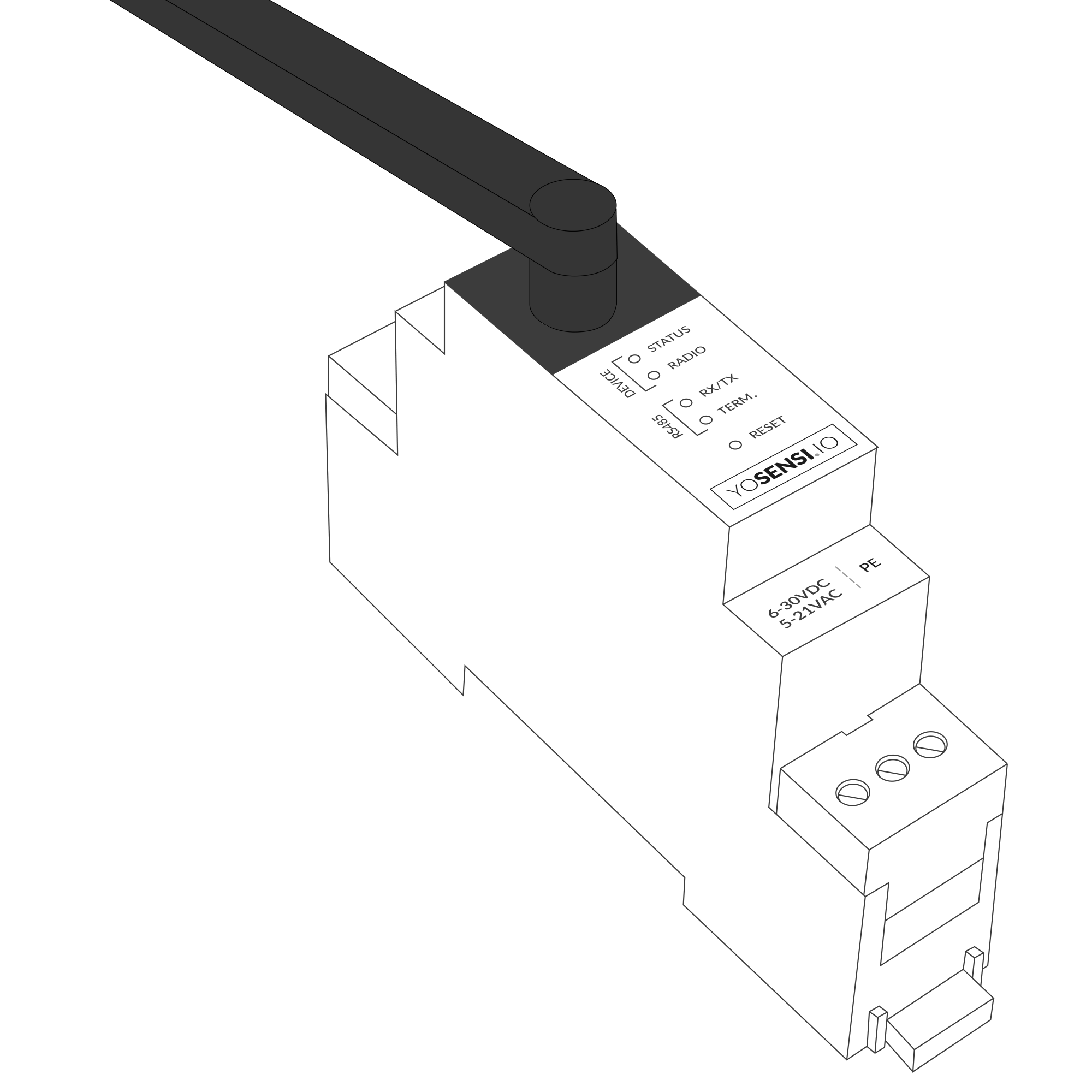
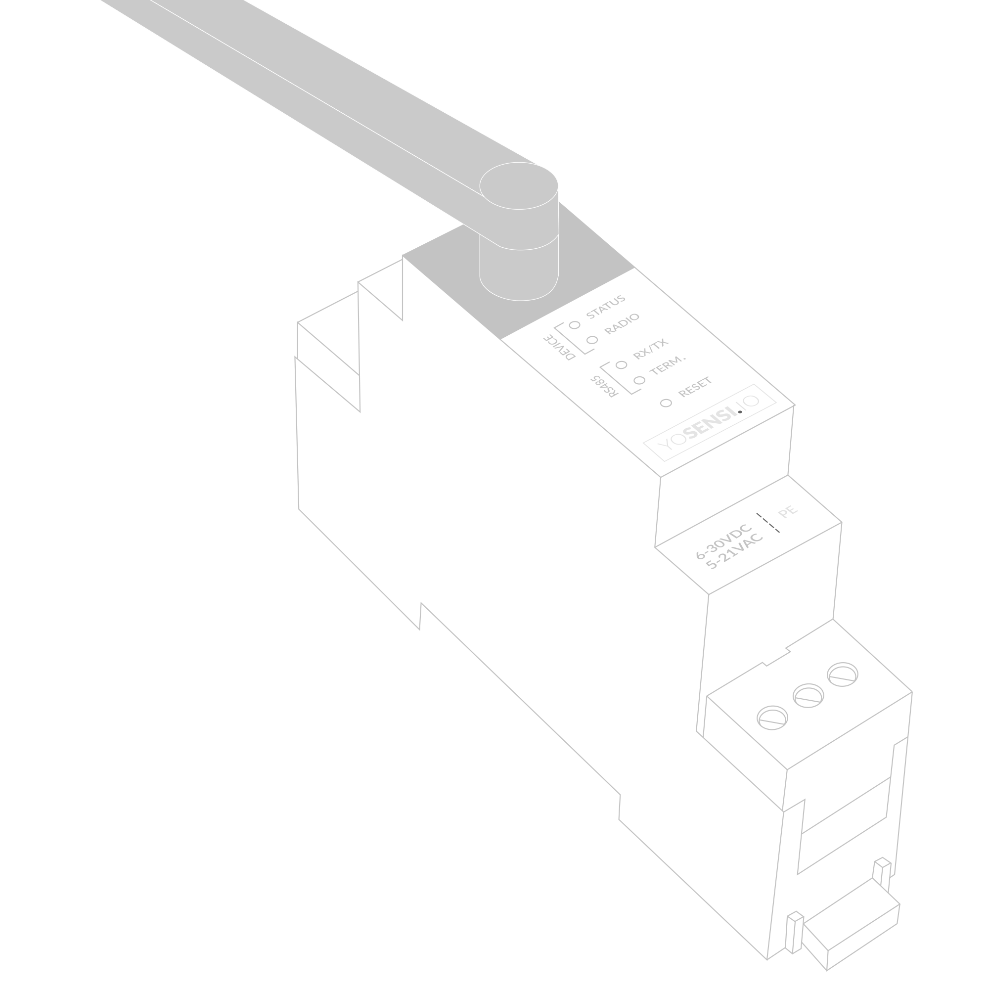
Figure 8. Device with antenna
Configuration
Configurable Parameters
A few parameters must be set before sending data to the gateway. The default firmware is configured in OTAA mode with predefined deveui, appkey (OTAA) and appskey, nwkskey (ABP).
Configuration of the device is stored in a JSON file divided into the following sections:
- info (generic, read only): information about the device,
- lorawan (generic): configuration data for LoRaWAN connection,
- ble (generic): Bluetooth settings,
- device (dynamic): individual configuration for a specific device (this section’s structure differs for each device),
- modbus (dynamic): individual configuration of Modbus RTU communication,
- serial (dynamic): asynchronous serial communication parameters for Modbus RTU protocol,
- timings (dynamic): timings for response and delays between master-slave communications,
- queries (dynamic): queries configured and executed by the user,
- pollstosend (dynamic): polls sent by slave to the master; data collections prepared to send via LoRaWAN,
Sample configuration file for the YO Modbus device.
{
	"info": {
		"devmodel": "LNRM",
		"fwver": "3.6.3",
		"loraradio": "SX1261",
		"lorawanver": "1.0.2",
		"loraregion": "EU868",
		"blemacaddr": "0123456789ab"
	},
	"lorawan": {
		"subband": 1,
		"nwktype": "public",
		"acttype": "otaa",
		"otaa": {
			"deveui": "0123456789abcdef",
			"appeui": "fedcba9876543210",
			"appkey": "000102030405060708090a0b0c0d0e0f",
			"trials": 3
		},
		"abp": {
			"devaddr": "01234567",
			"nwkskey": "0123456789abcdef0123456789abcdef",
			"appskey": "000102030405060708090a0b0c0d0e0f"
		}
	},
	"ble": {
		"power": 0,
		"interval": 1600
	},
	"device": {
		"measinterval": 600,
	},
	"modbus": {
		"terminationresistor": false,
		"driverswitchidletime": 5
	},
	"serial": {
		"baudrate": 9600,
		"databits": 8,
		"parity": "none",
		"stopbits": 1
	},
	"timings": {
		"responsetimeout": 1000,
		"delaybetweenpolls": 100
	},
	"queries": [
		{
		"name": "01Ph1V",
		"slaveaddr": 1,
		"funccode": 3,
		"startreg": "1000",
		"regnbr": 2
		},
		{
		"name": "RunHour",
		"slaveaddr": 1,
		"funccode": 3,
		"startreg": "106e",
		"regnbr": 1
		},
		{
		"name": "3PHpwrfctr",
		"slaveaddr": 1,
		"funccode": 3,
		"startreg": "1024",
		"regnbr": 1
		},
		{
		"name": "1PHactpwr",
		"slaveaddr": 1,
		"funccode": 3,
		"startreg": "102c",
		"regnbr": 2
		}
	],
	"pollstosend": [
		{
			"cnt": 1,
			"out": [
				"01Ph1V",
				"RunHour",
				"3PHpwrfctr",
				"1PHactpwr"
			]
		}
	]
}
OTAA & ABP
| OTAA | ABP |
|---|---|
| Device EUI | Device Address |
| Application EUI | Network Session Key |
| Application Key | Application Session Key |
| Number of Trials |
Generic Parameters
Click here to see the generic parameters for Yosensi devices.
Parameters
Device Parameters
| Name | Description | Possible Values | Default Value | Read/Write |
|---|---|---|---|---|
| measinterval | Measuring and sending interval LoRa [s] | 601-999999 | 600 | R/W |
| ||||
Modbus Parameters
| Name | Description | Possible Values | Default Value | Read/Write |
|---|---|---|---|---|
| terminationresistor | Presence of termination resistor in RS485 standard | true, false | false | R/W |
| driverswitchidletime | Delay [ms] of TX and RX parameters in serial communication between devices in the network | 1-100 | 5 | R/W |
Serial and Timings Parameters
| Name | Description | Possible Values | Default Value | Read/Write |
|---|---|---|---|---|
| baudrate | Bus speed [bps] | 1200, 2400, 4800, 9600 | 9600 | R/W |
| databits | Number of data bytes per packet | 7, 8, 9 | 8 | R/W |
| parity | Data integrity validation type | none, odd, even | none | R/W |
| stopbits | Last bit type of a one-byte transmission | 1, 2 | 1 | R/W |
| responsetimeout | Response timeout from slave device in [ms] | 10-10000 | 1000 | R/W |
| delaybetweenpolls | Delay [ms] before the next query | 1-10000 | 100 | R/W |
Queries and Polls Parameters
| Name | Description | Possible Values | Default Value | Read/Write |
|---|---|---|---|---|
| name | Name of query, up to 10 characters | “0-9, A-Z, a-z, _, . ,” e.g. aB.cD-01 | - | R/W |
| slaveaddr | Number of slave addresses to communicate with | 0-255 | 1 | R/W |
| funccode | Supported Modbus function codes | 1, 2, 3, 4 | 3 | R/W |
| startreg | Start register to read data from | 2B (HEX), e.g. 1000 | - | R/W |
| regnbr | Number of words (2 bytes) to read from registers, begins from ’startreg’ | 1-8 | 1 | R/W |
| cnt | LoRa packet collection index number. Each packet can contain 5 queries. | 1-30 | - | R/W |
| out | Name of the query to be transmitted in a LoRa packet | “0–9 A–Z a–z . ,” e.g. aB.cD-01 | - | R/W |
Parameters description
- nwktype: used for setting the device in public or private network type.
- acttype: used for setting the device in ABP or OTAA mode.
- deveui, … , appskey: predefined addresses and keys, these parameters are generated using multiple IDs specific to the particular MCU and are unique for each device. They can be changed if needed.
- interval: determines the interval of sending broadcast packets, used to connect to every BLE receiver around the device.
- subband: used for setting the communication frequency sub-band in LoRaWAN.
- measinterval: measurement interval [s] between sending LoRa packets.
- teminationresistor: whether a resistor is applied to the end line to prevent signal reflections for correct signal transmission. Value “TRUE” means that the resistor is installed.
- driverswitchiddletime: Delay [ms] from 1 ms up to 100 ms for serial TX and RX parameters between devices in the network.
- baudrate: information transfer rate bits per second. Supported baud rates are 1200, 2400, 4800, 9600.
- databits: the amount of data in each packet. 7, 8, 9 formats are not supported with parity “none” value.
- parity: The parity bit, unlike the start and stop bits, is an optional parameter, used in serial communications to determine if the data character being transmitted is correctly received by the remote device.
- stopbits: the last bit of a one-byte transmission, used for timing or synchronization.
- responsetimeout: how long Modbus Poll should wait for a slave device response before giving up. Default is 1000 ms.
- delaybetweenpolls: the minimum delay until the next request is transmitted. Default is 100 ms.
- name: name of the query parameter, up to 10 characters. The name can be freely modified by the user to correspond to the parameter to be read out.
- slaveaddr: address of the target slave device.
- funccode: function code for the Modbus RTU protocol. Value 1 indicates “read coils”, value 2 = “read contacts”, 3 = “read holding registers”, 4 = “read input registers”.
- startreg: starting register, which is the address from which the reading of data from a particular slave will start.
- regnbr: register number of data to read from the slave. Value “1” means that 2 bytes will be read, value “2” = 4 bytes will be read over the Modbus network..
- cnt: packet counter index. The YO Modbus device can handle up to 150 queries. Limitation is 5 variables per query.
- out: the query name for the output of the slave. Maximum of 5 queries per packet (along with maximum of 150 queries per Modbus).
Downlink message
You can remotely adjust certain parameters by sending a downlink message through our platform. Simply navigate to the "COMMANDS" section for the selected device.
Update Measurement Interval
It is possible to change the measurement interval (measinterval) by using downlink. Information about changing the parameter will be sent from the server via the gateway.
Example of Downlink Message:
- Prefix:
0x03 - Measurement Index:
0x00 - Data (up to 4 bytes in hex):
0258
Sample Downlink: 0x03000258 - Sets a measurement interval of 600 seconds (10 minutes).
Click here to see how to connect a node using the Yosensi Management Platform.
See how to configure a node in Yosensi Management Platform
Check how to adopt and configure a node via the Yosensi App.
Take a look at the list of frequency plans used in Yosensi.
This datasheet describes the payload protocol developed by Yosensi for communicating with our devices.
Payload Decoder
If you want to connect to your own server, it is necessary to decode the specific payload for each device. To accomplish this, a payload decoder is required, which can be downloaded using the following link: Payload decoder. You can also use our integrated Payload Decoder here. Extended documentation of the protocol can be found in the Payload description on our website.
Compliance Statements
To view or download the Declaration of Conformity for YO Modbus go here