YO Relay Switch
Overview
Description
The YO Relay Switch is a remotely controlled LoRaWAN switch with two control channels, capable of transmitting the state of its input and controlling its output. Operating in LoRa Class C, the device can continuously listen beyond short data transmission periods. Ideal for building management, agriculture, and industrial applications, the YO Relay Switch is scalable, allowing the management of two units within a single network. It is used for applications such as remote control of lighting, heating, and cooling, efficient management of HVAC, lighting, and security systems, automation of irrigation and ventilation in agriculture, and monitoring and control of machinery in industrial settings. The device integrates easily via BLE and is managed through the free Yosensi Mobile Application for seamless monitoring and control.
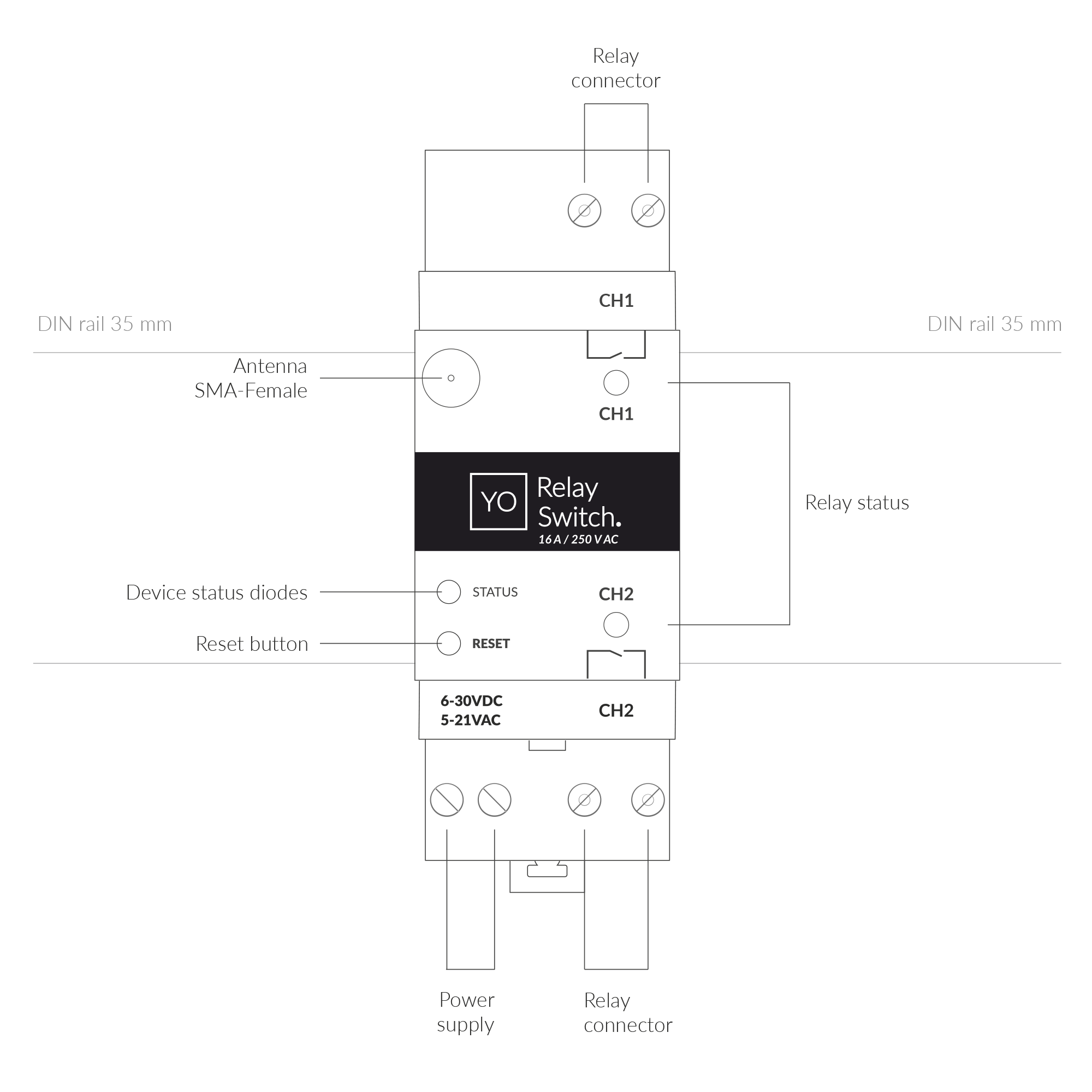
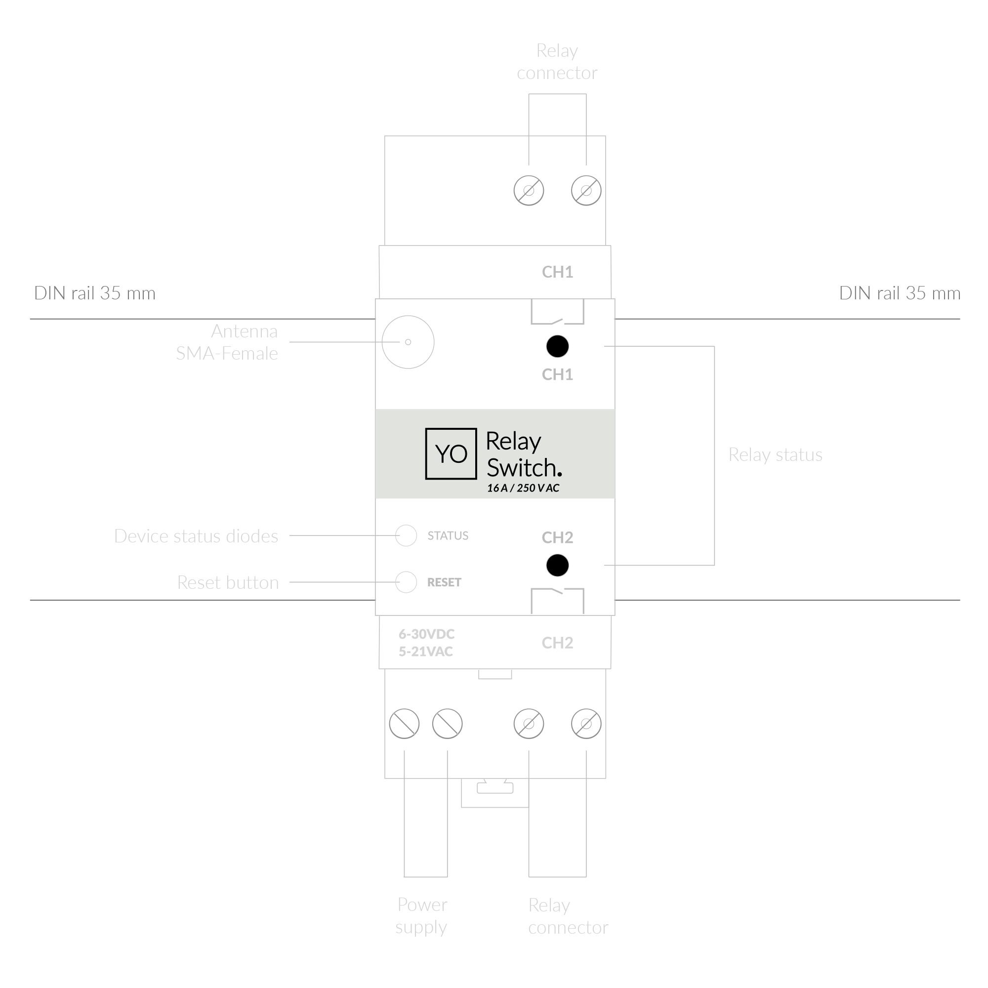
Figure 1. Device top view
Device sticker placed on the right side of the device enclosure contains information about model, version, LoRaWAN region and 3 parameters important in case of device identification and configuration:
- DEV EUI: 64-bit unique device identifier in a LoRaWAN network,
- DEV ADDR: address required to connect via ABP activation type to LoRaWAN,
- BLE MAC: Bluetooth physical address.
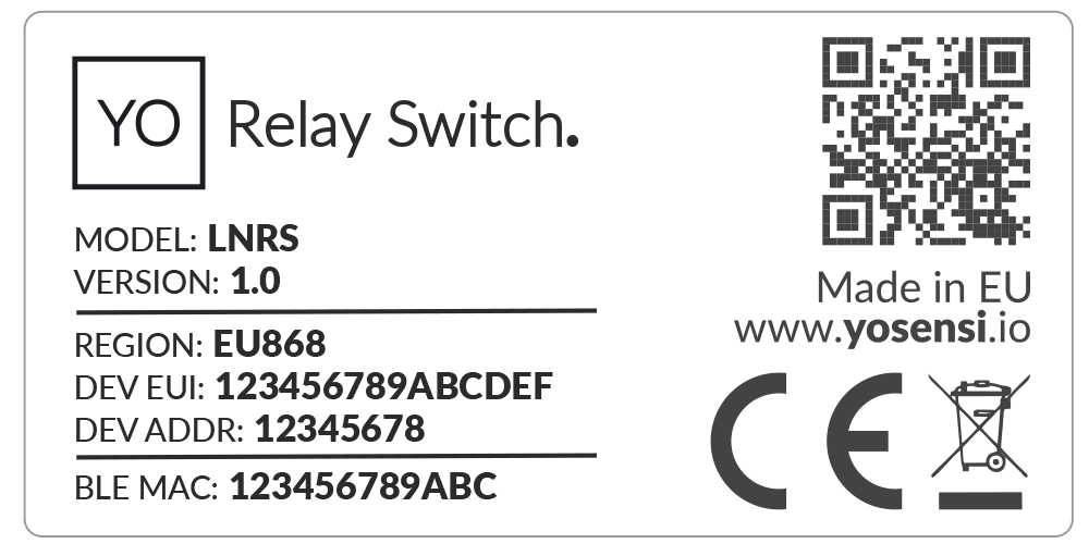
Figure 2. Device sticker
Features
- LoRaWAN Technology: Available in multiple versions with LoRa radio configured for various regions and ISM frequency bands (e.g., EU868, US915, AU915), it is compatible with both private and public LoRaWAN networks and supports connections via ABP (Activation by Personalization) or OTAA (Over-The-Air Activation).
- Bluetooth Low Energy (BLE): Enables easy configuration through a user-friendly JSON data exchange format, supports firmware updates via OTA (Over-the-Air), and boasts very low energy consumption.
- Internal Voltage: Provides a monitoring solution for the device internal voltage.
- Relay State Channels: Displays the current state of each relay channel for precise monitoring and control.
- Yosensi Management Platform: Provides a web tool for device configuration, firmware updates, and infrastructure management. Enables comprehensive monitoring of transmitted data and easy device management.
- Yosensi Mobile App: Effortlessly manage devices with features to register new ones, configure settings, perform firmware updates, view/send logs, and test LoRaWAN connectivity. Learn more in our detailed Yosensi App blog post.
Specifications
Physical
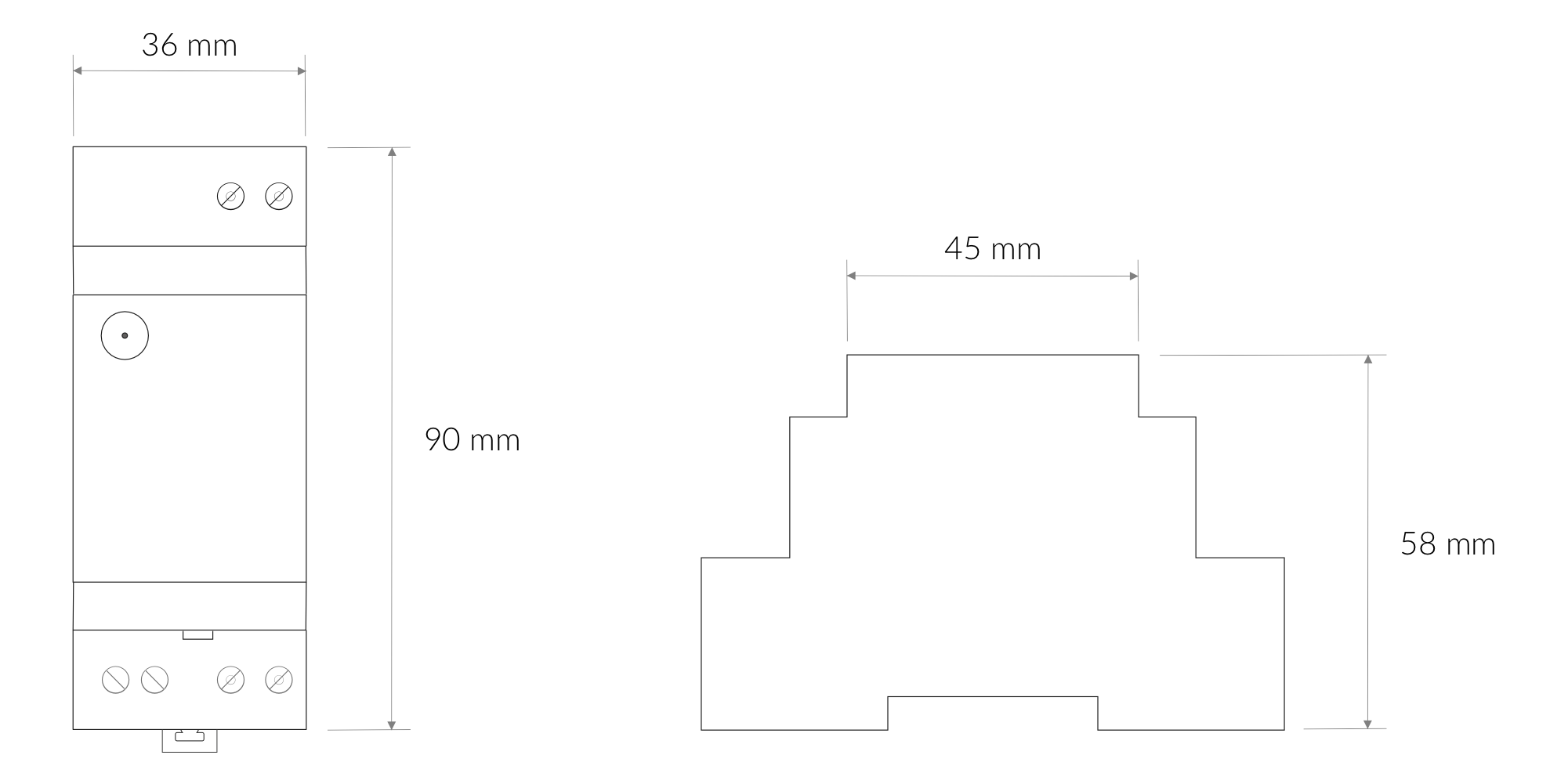
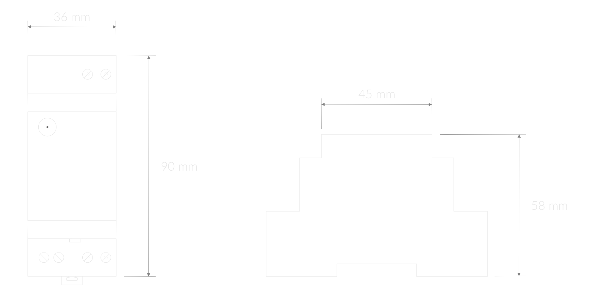
Figure 3. Dimensions of the device
Device
| Attribute | Description |
|---|---|
| Dimensions | Height: 90 mm Width: 36 mm (2-pole) Depth: 58 mm |
| Colour | Light Grey |
| Mounting method | 35 mm DIN rail standard |
| Enclosure material | Polycarbonate |
| Level of protection | IP20, UL94-VO |
| Weight | 120 g |
Operating Conditions
| Attribute | Description |
|---|---|
| Temperature | 0°C to 70°C |
| Humidity | 0 to 90% |
| Placement | Indoor use |
| Power supply | 6-30 V DC 5-21 V AC |
| Power consumption | Typical: 18 mA DC (12 V DC) Maximum: 250 mA DC (12 V DC) |
Measured Values
| Parameter | Measurement range | Accuracy |
|---|---|---|
| Voltage | - | - |
| Relay State Channel 1 | 0-1 | - |
| Relay State Channel 2 | 0-1 | - |
Controls and Indicators
LED Status Indicator
YO Relay Switch communicates its current behaviour to the user by RGBW LED placed on the top.
Diode statuses interpretation
| Behavior | Colour | Status |
|---|---|---|
| Single flash | Green | General: device is working correctly (power and memory). |
| Single flash | Red | General: device is working incorrectly (power and memory). LoRaWAN communication: failed to receive an acknowledgement from LoRaWAN Server within specified timeout. |
| Single flash | White | LoRaWAN communication: LoRaWAN frame sent / confirmation from LoRaWAN Server after receiving the frame. |
| Slow flashing | Blue | BLE communication: connection to the device via BLE (configuration). |
| Rapid flashing | Blue | LoRaWAN communication: connecting to LoRaWAN network. |
| Continuous lit | Orange | Term diode: Terminating resistor connected. |
| Relay Chx lit | Off | Relay status: Relay set OFF. |
| Green | Relay status: Relay set ON. |
Buttons
The YO Relay Switch has a button for resetting the device. Figure 4 shows its placement. To reboot the device, press the reset button for a moment.
Figure 4. Reset button
Installation
Package Contents
- Device.
- Antenna.
- Warranty card.
Safety Precautions
Go to the Safety Precautions section to see important information on handling, disposal and maintenance.
Installation Guide
- Mount the device on a 35 mm DIN rail.
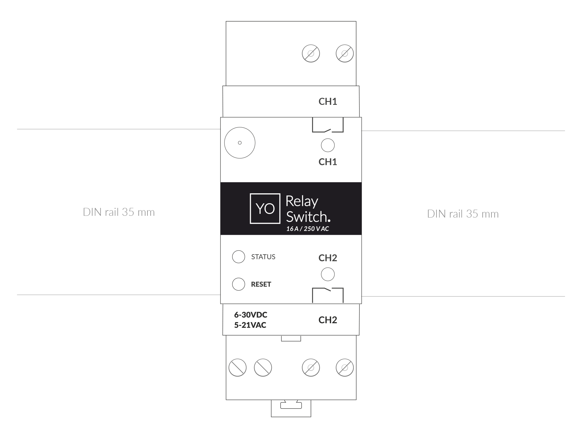
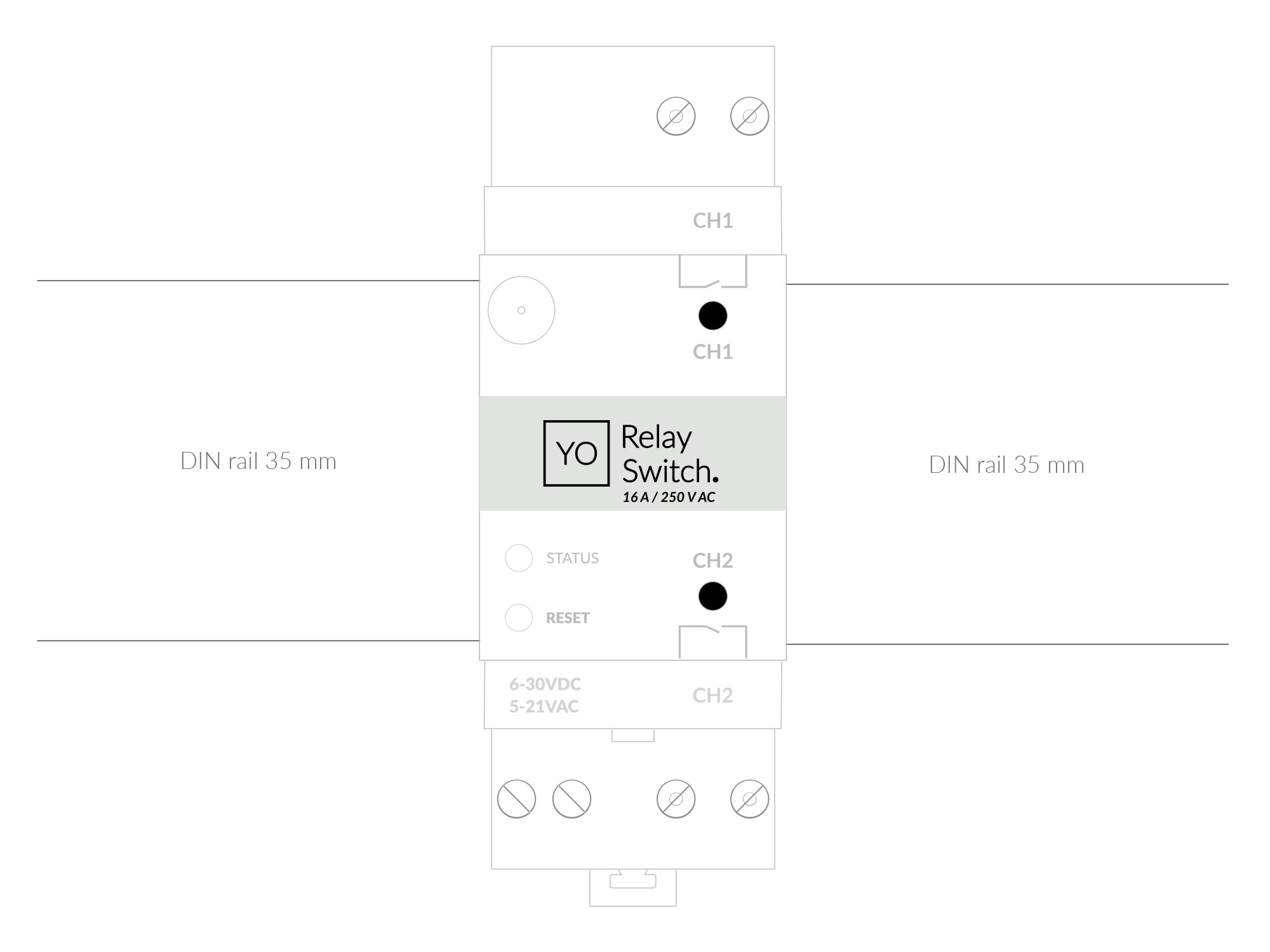
Figure 5. Device mounted on 35 mm DIN rail
- Connect the antenna to the device.
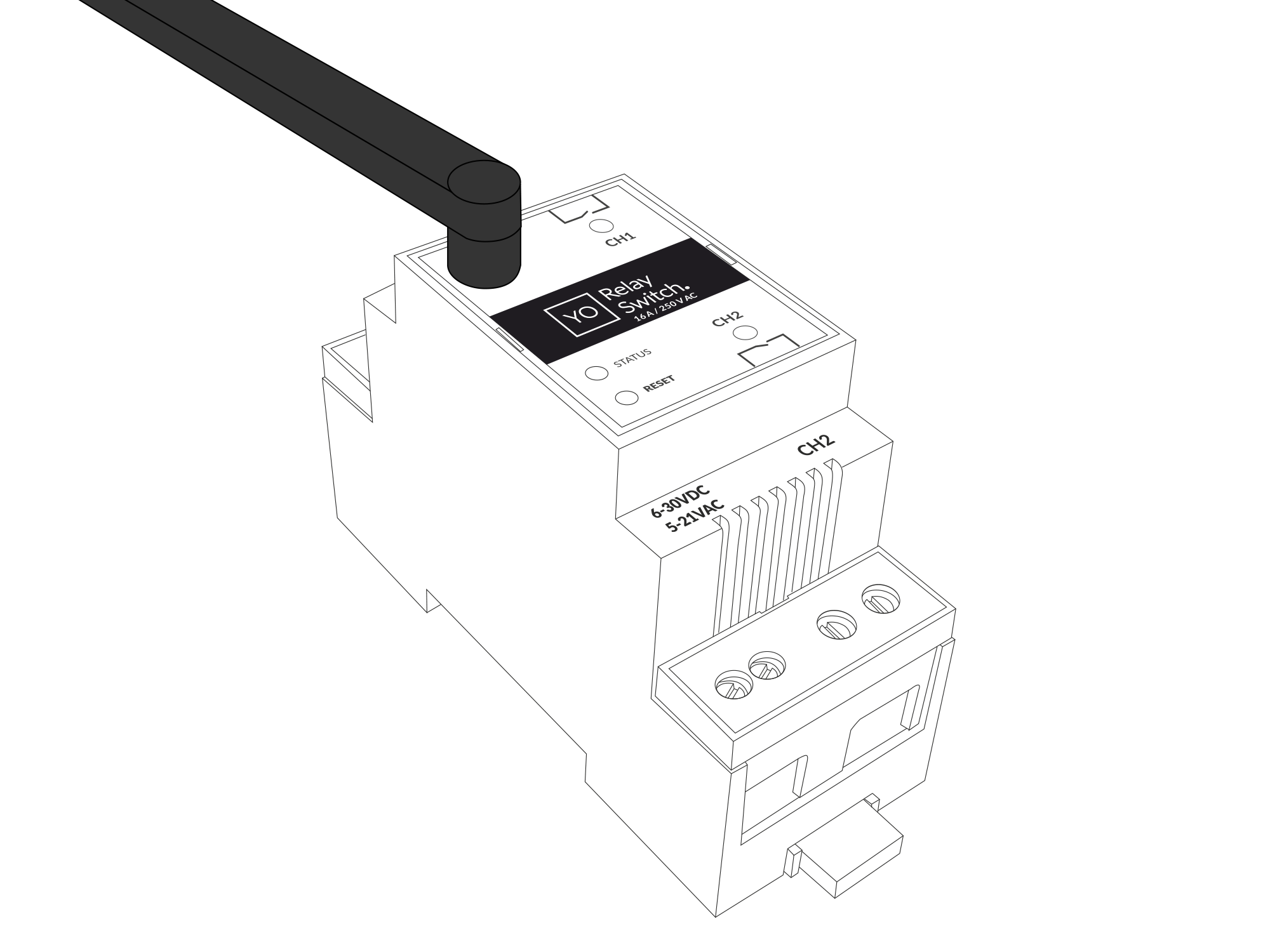
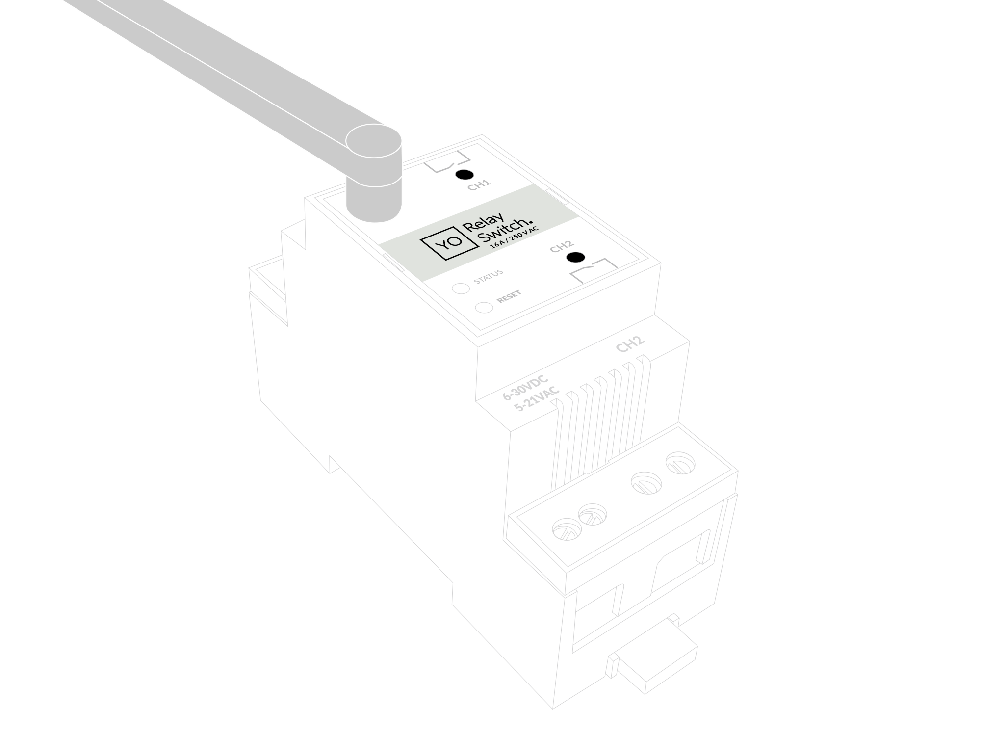
Figure 6. Device with antenna
- Screw the load wires to the device at the designated locations for the first channel (CH1) and the second channel (CH2).
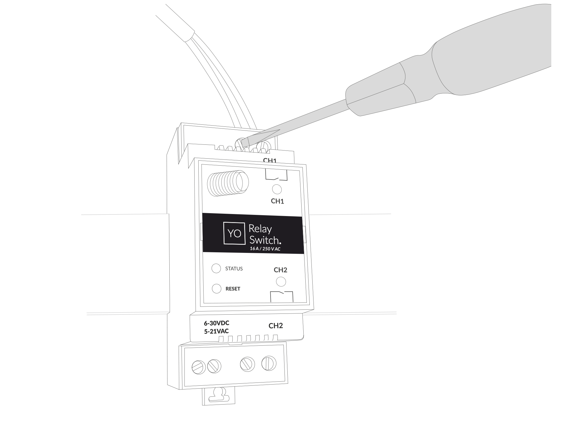
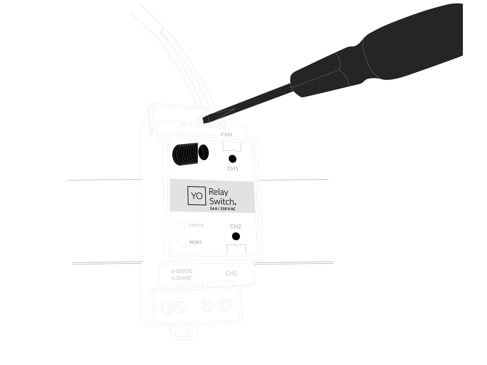
Figure 7. Connecting communication wires to device terminal blocks
- Screw the power supply wires to the device (6-30 V DC, 5-21 V AC). Once power is connected, the indicator diodes should behave as described in LED Status Indicator.
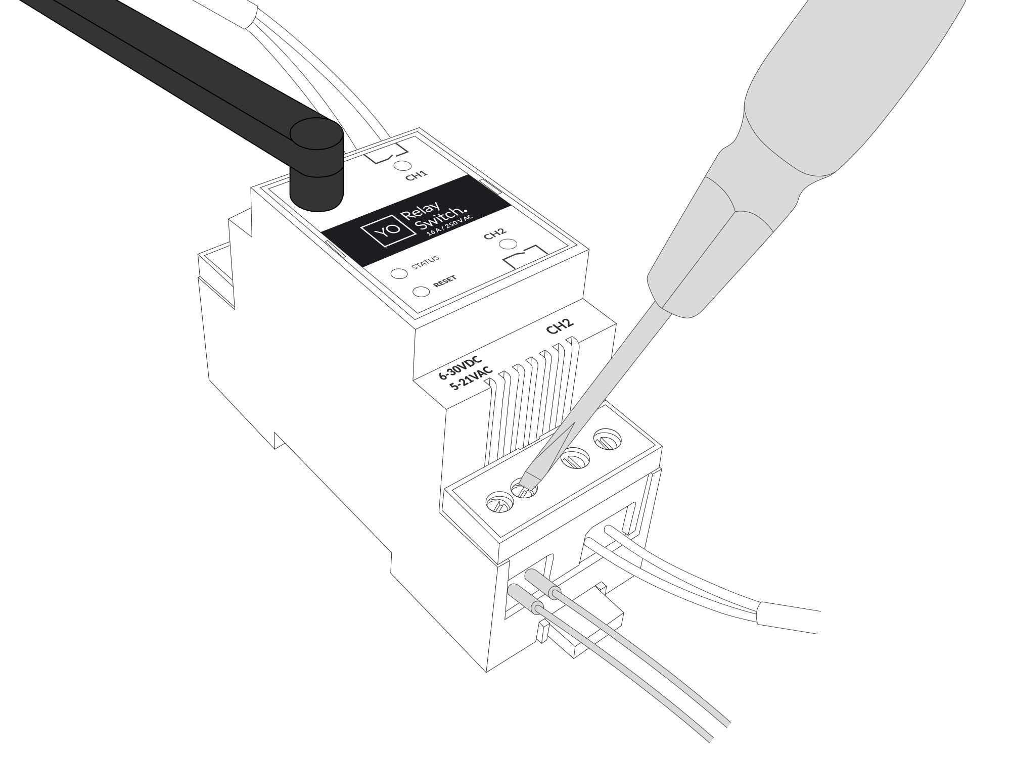
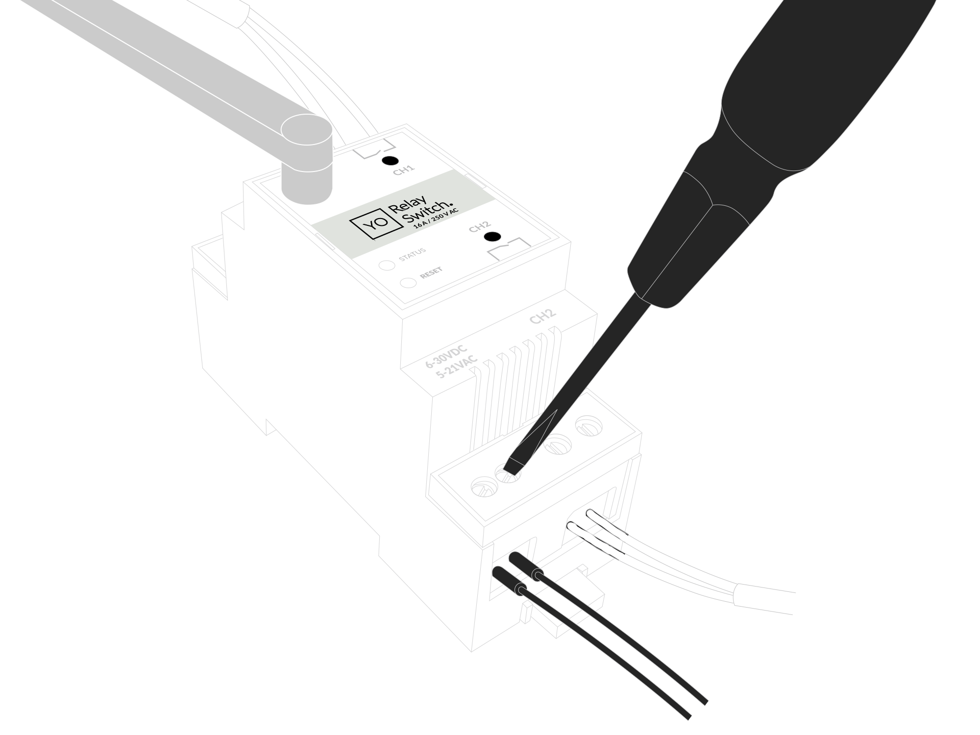
Figure 8. Connecting power supply to the device
Configuration
Configurable Parameters
A few parameters must be set before sending data to the gateway. The default firmware is configured in OTAA mode with predefined deveui, appkey (OTAA) and appskey, nwkskey (ABP).
Configuration of the device is stored in a JSON file divided into the following sections:
- info (generic, read only): information about the device,
- general (generic): general device settings,
- lorawan (generic): configuration data for LoRaWAN connection,
- ble (generic): Bluetooth settings,
- device (dynamic): individual configuration for a specific device (this section’s structure differs for each device),
Sample configuration file for the YO Relay Switch device.
{
	"info": {
		"devmodel": "LNRS",
		"fwver": "1.0.0",
		"loraradio": "SX1261",
		"lorawanver": "1.0.2",
		"loraregion": "EU868",
		"blemacaddr": "0123456789ab"
	},
	"general": {
		"rtcstate": "disable"
	},
	"lorawan": {
		"subband": 1,
		"nwktype": "public",
		"acttype": "otaa",
		"otaa": {
			"deveui": "0123456789abcdef",
			"appeui": "fedcba9876543210",
			"appkey": "000102030405060708090a0b0c0d0e0f",
			"trials": 3
		},
		"abp": {
			"devaddr": "01234567",
			"nwkskey": "0123456789abcdef0123456789abcdef",
			"appskey": "000102030405060708090a0b0c0d0e0f"
		}
	},
	"ble": {
		"power": 0,
		"interval": 1600
	},
	"device": {
		"measinterval": 1800,
		"channels": [
			{
				"channel": 1,
				"outputmode": "no"
			},
			{
				"channel": 2,
				"outputmode": "no"
			},
		]
	}
}
OTAA & ABP
| OTAA | ABP |
|---|---|
| Device EUI | Device Address |
| Application EUI | Network Session Key |
| Application Key | Application Session Key |
| Number of Trials |
Generic Parameters
Click here to see the generic parameters for Yosensi devices.
Parameters
Device Parameters
| Name | Description | Possible Values | Default Value | Read/Write |
|---|---|---|---|---|
| measinterval | Measuring and sending interval LoRa [s] | 601-999999 | 300 | R/W |
| channel | Relay channel number | 1-14 | 1 | R/W |
| outputmode | Output type normally open/closed | no, nc | no | R/W |
| ||||
Parameters description
- rtcstate: used for enabling/disabling the real-time clock (RTC) inside the device. The RTC is used for timestamping the measurements.
- nwktype: used for setting the device in public or private network type.
- acttype: used for setting the device in ABP or OTAA mode.
- deveui, … , appskey: predefined addresses and keys, these parameters are generated using multiple IDs specific to the particular MCU and are unique for each device. They can be changed if needed.
- interval: determines the interval of sending broadcast packets, used to connect to every BLE receiver around the device.
- subband: used for setting the communication frequency sub-band in LoRaWAN.
- measinterval: measurement interval [s] between sending LoRa packets.
- channel: Relay channel number.
- outputmode: Output mode selection. Set as normally open “no” or normally closed “nc”.
Downlink message
You can remotely adjust certain parameters by sending a downlink message through our platform. Simply navigate to the "COMMANDS" section for the selected device.
Update Measurement Interval
It is possible to change the measurement interval (measinterval) by using downlink. Information about changing the parameter will be sent from the server via the gateway.
Example of Downlink Message:
- Prefix:
0x03 - Measurement Index:
0x10 - Data (up to 4 bytes in hex):
0258
Sample Downlink: 0x03100258 - Sets a measurement interval of 600 seconds (10 minutes).
Update Channel Mode
It is possible to change the channel mode by using downlink.
Example of Downlink Message:
- Prefix:
0x03 - Measurement Index:
0xfd - Channel Number [1 byte]:
0x01 - Channel Value [1 byte]:
0x01
Sample Downlink: 0x03fd0101 - Sets the channel 1 mode to 1.
Update Relay State without ACK
It is possible to change the relay state of a specified channel by using downlink.
Example of Downlink Message:
- Prefix:
0x03 - Measurement Index:
0xfe - Channel Number [1 byte]:
0x01 - Channel Value [1 byte]:
0x01
Sample Downlink: 0x03fe0101 - Sets the relay state of channel 1 to 1.
Update Relay State with ACK
It is possible to change the relay state of a specified channel by using downlink.
Example of Downlink Message:
- Prefix:
0x03 - Measurement Index:
0xff - Channel Number [1 byte]:
0x01 - Channel Value [1 byte]:
0x00
Sample Downlink: 0x03ff0100 - Sets the relay state of channel 1 to 0 and sends an ACK.
Click here to see how to connect a node using the Yosensi Management Platform.
See how to configure a node in Yosensi Management Platform
Check how to adopt and configure a node via the Yosensi App.
Take a look at the list of frequency plans used in Yosensi.
This datasheet describes the payload protocol developed by Yosensi for communicating with our devices.
Payload Decoder
If you want to connect to your own server, it is necessary to decode the specific payload for each device. To accomplish this, a payload decoder is required, which can be downloaded using the following link: Payload decoder. You can also use our integrated Payload Decoder here. Extended documentation of the protocol can be found in the Payload description on our website.