YO Particulate Matter Sensor
Overview
Description
YO Particulate Matter Sensor is a LoRaWAN device designed for high-precision air quality monitoring. It measures particulate matter (PM) levels, including mass concentration for PM1, PM2.5, PM4, and PM10, while providing detailed particles concentration data for PM1 and PM2.5. With its advanced algorithm meeting firm environmental standards, the device delivers reliable and accurate air quality data. Powered by two lithium thionyl chloride D-size batteries, the YO Particulate Matter Sensor ensures long-lasting operation even in remote locations. It also includes temperature and humidity sensors, providing environmental context around the device’s location for informational purposes.
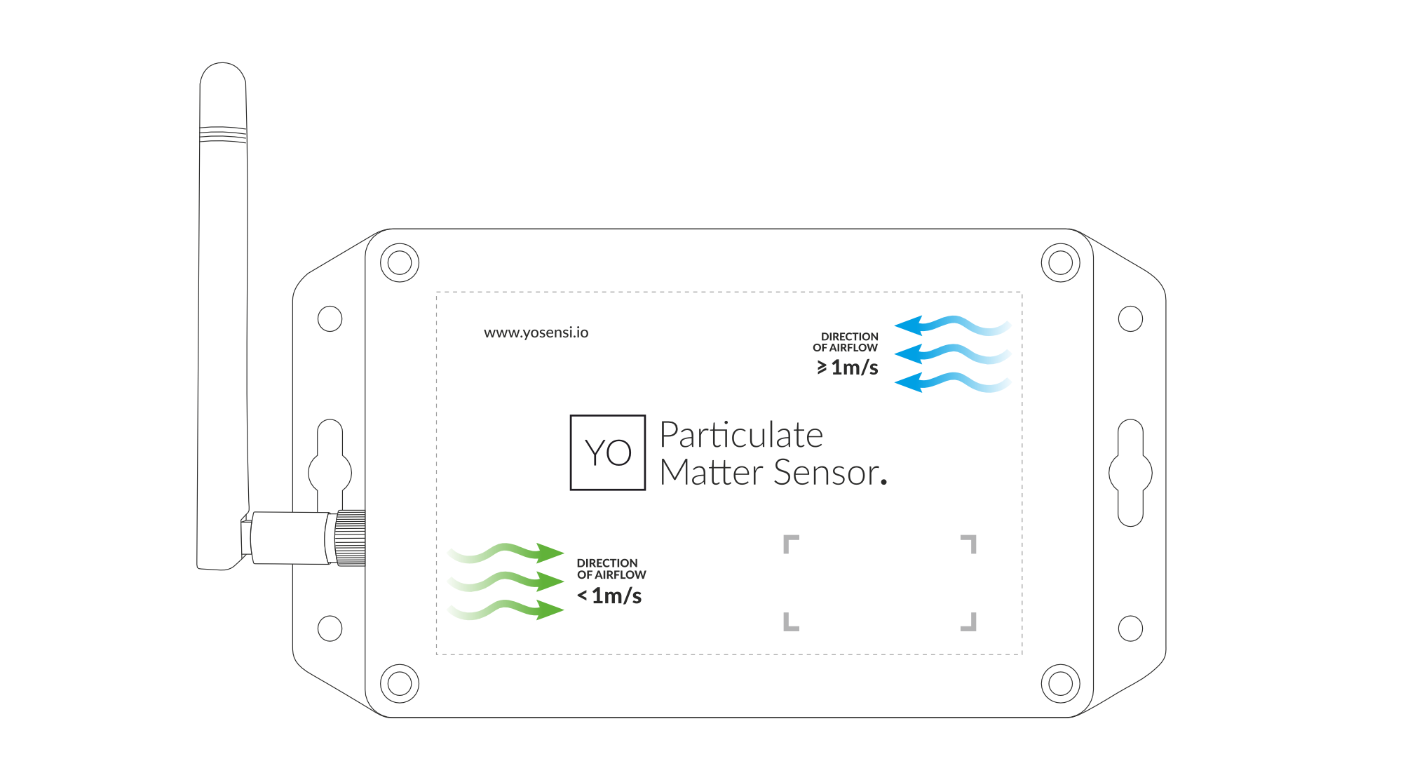
Figure 1. Device top view
Device sticker placed on top and bottom of the enclosure contains information about model, version, LoRaWAN region and 3 parameters important in case of device identification and configuration:
- DEV EUI: 64-bit unique device identifier in a LoRaWAN network,
- DEV ADDR: address required to connect via ABP activation type to LoRaWAN,
- BLE MAC: bluetooth physical address.
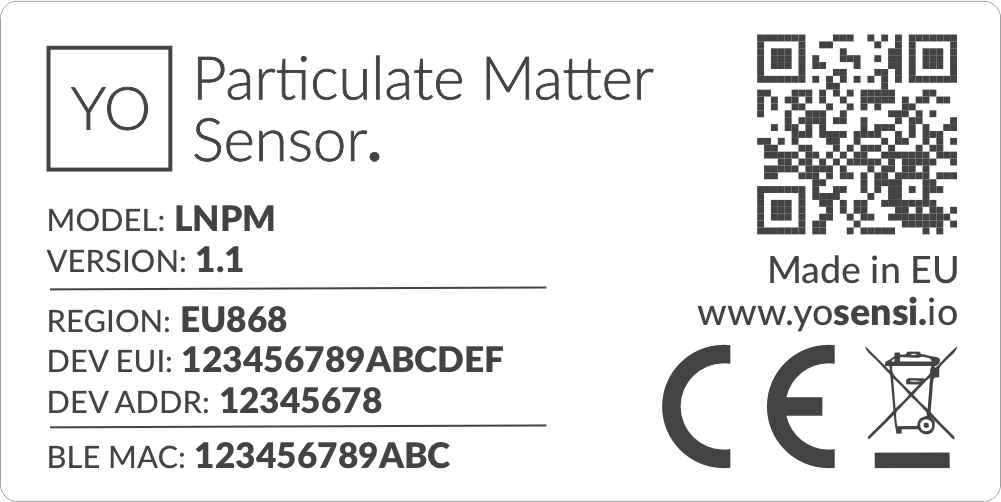
Figure 2. Device sticker
Features
- LoraWAN Technology: Available in multiple versions with LoRa radio configured for various regions and ISM frequency bands (e.g., EU868, US915, AU915), it is compatible with both private and public LoRaWAN networks and supports connections via ABP (Activation by Personalization) or OTAA (Over-The-Air Activation).
- Bluetooth Low Energy (BLE): Enables easy configuration through a user-friendly JSON data exchange format, supports firmware updates via OTA (Over-the-Air), and boasts very low energy consumption.
- Battery-Powered: 2 x ER34615 (D) LiSoCL2 batteries featuring very low self-discharge, ensuring long-term operation without the need for an external power supply.
- Temperature and Relative Humidity: Measured by sensors within the device enclosure, using a vent to allow external air entry, providing insights into environmental conditions and ensuring operation within recommended parameters.
- PM Sensor: Informs users about the quantity of PM1, PM2.5, PM4, and PM10, while also providing insights into surrounding air pollution through analysis of these measurements.
- Accelerometer: Provides the position of the device in X, Y, and Z axes, and uses the accelerometer to indicate the position during PM measurements.
- Yosensi Management Platform: Provides a web tool for device configuration, firmware updates, and infrastructure management. Enables comprehensive monitoring of transmitted data and easy device management.
- Yosensi Mobile App: Effortlessly manage devices with features to register new ones, configure settings, perform firmware updates, view/send logs, and test LoRaWAN connectivity. Learn more in our detailed Yosensi App blog post.
Specifications
Physical
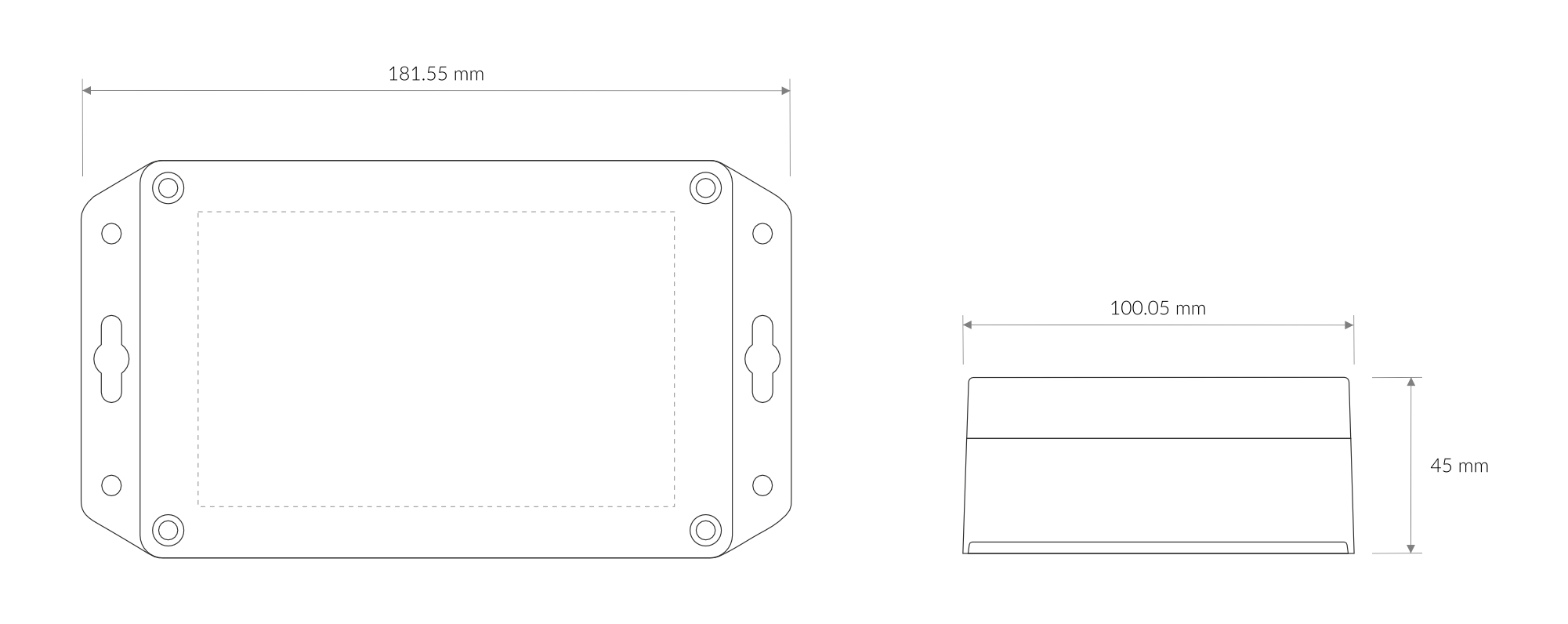
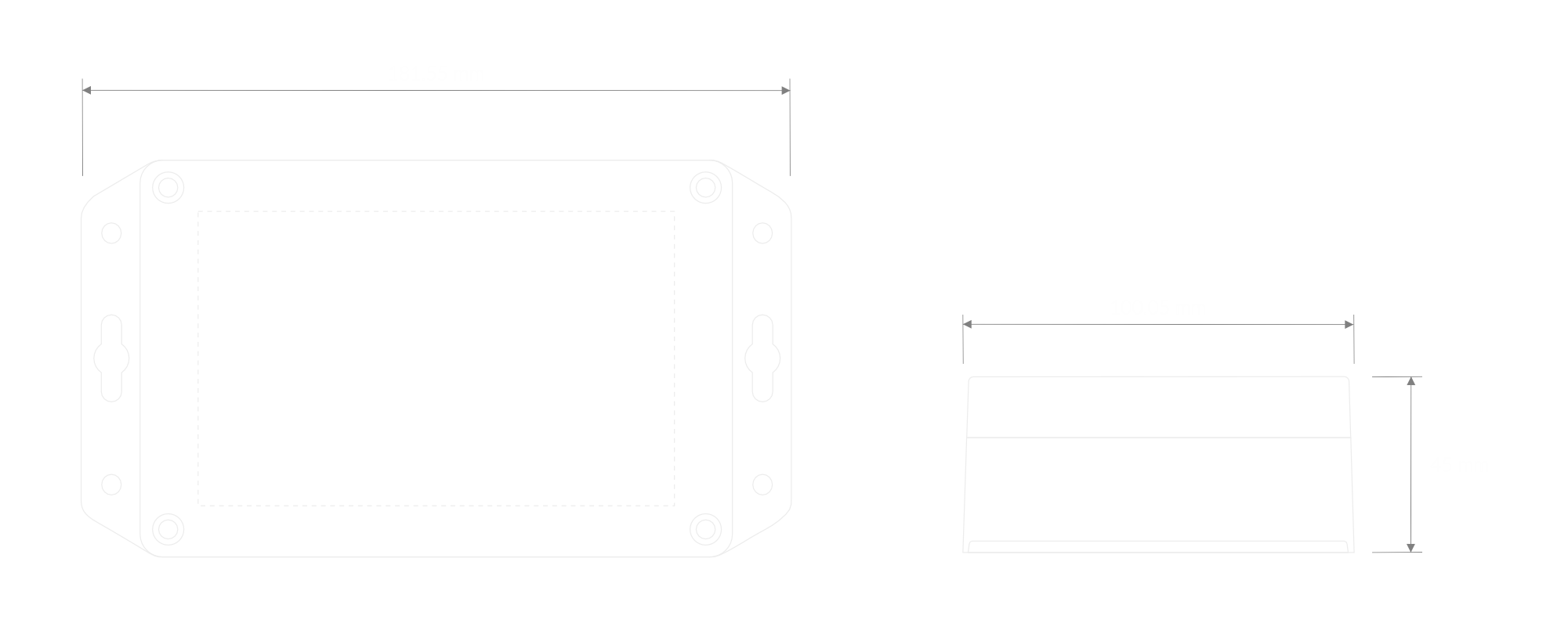
Figure 3. Dimensions of the device
Device
| Attribute | Description |
|---|---|
| Dimensions | Height: 45 mm Width: 101.5 mm Depth: 181.5 mm |
| Colour | Light Grey |
| Mounting method | Magnets on the back Mounting holes |
| Enclosure material | ABS, PC |
| Level of protection | IP20, UL94-V2 |
| Weight | 410 g (without batteries) |
Operating Conditions
| Attribute | Description |
|---|---|
| Temperature | 0°C to 70°C |
| Humidity | 0 to 90% |
| Placement | Indoor use |
| Power supply | 2 x ER34615 (Size D) LiSoCL2 battery (2 x 3.6 V) |
| Power consumption | Maximum: 120 mA DC (7.2 V DC) |
Measured Values
| Parameter | Measurement range | Accuracy |
|---|---|---|
| Temperature | -40°C to 125°C | ±0.2°C (10°C to 60°C) |
| Relative humidity | 0% to 100% | ±2% (20% to 80%) |
| Mass Concentration PM1 & PM2.5 | 0 to 100 μg/m³ 100 to 1000 μg/m³ | ±5 μg/m3 + 5 % m.v. ±10 % m.v. (at 25°C) |
| Particles Concentration PM1 & PM2.5 | 0 to 1000 #/cm³ 1000 to 3000 #/cm³ | ±100 #/cm3 ±10 % m.v. (at 25°C) |
| Mass Concentration PM4 & PM10 | 0 to 100 μg/m³ 100 to 1000 μg/m³ | ±25 μg/m3 ±25 % m.v. (at 25°C) |
| Accelerometer | ±90° on X and Y axes 0-180° on Z axis | ±0.1° (-40°C - 85°C) |
Controls and Indicators
LED Status Indicator
YO Particulate Matter Sensor communicates its current behaviour to the user by RGBW LED placed on top.
Diode statuses interpretation
| Behavior | Colour | Device Status |
|---|---|---|
| Single flash | Green | General: device is working correctly (power and memory). |
| Single flash | Red | General: device is working incorrectly (power and memory). LoRaWAN communication: failed to receive an acknowledgement from LoRaWAN Server within specified timeout. |
| Single flash | White | LoRaWAN communication: LoRaWAN frame sent / confirmation from LoRaWAN Server after receiving the frame. |
| Slow flashing | Blue | BLE communication: connection to the device via BLE (configuration). |
| Rapid flashing | Blue | LoRaWAN communication: connecting to LoRaWAN network. |
Buttons
The YO Particulate Matter Sensor features a reset button and an LED indicator. Figure 4 illustrates their placement. To reboot the device, briefly press the reset button.
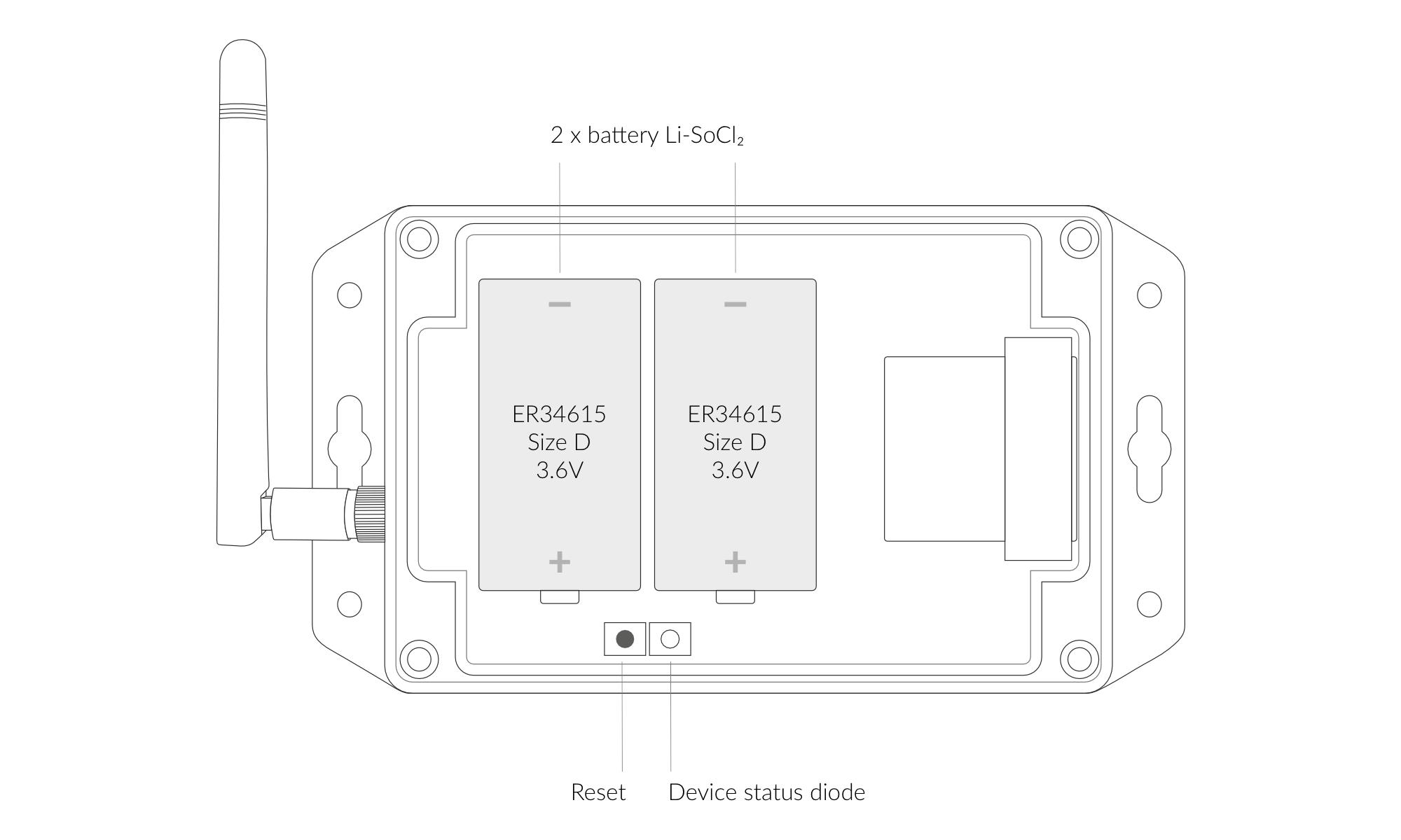
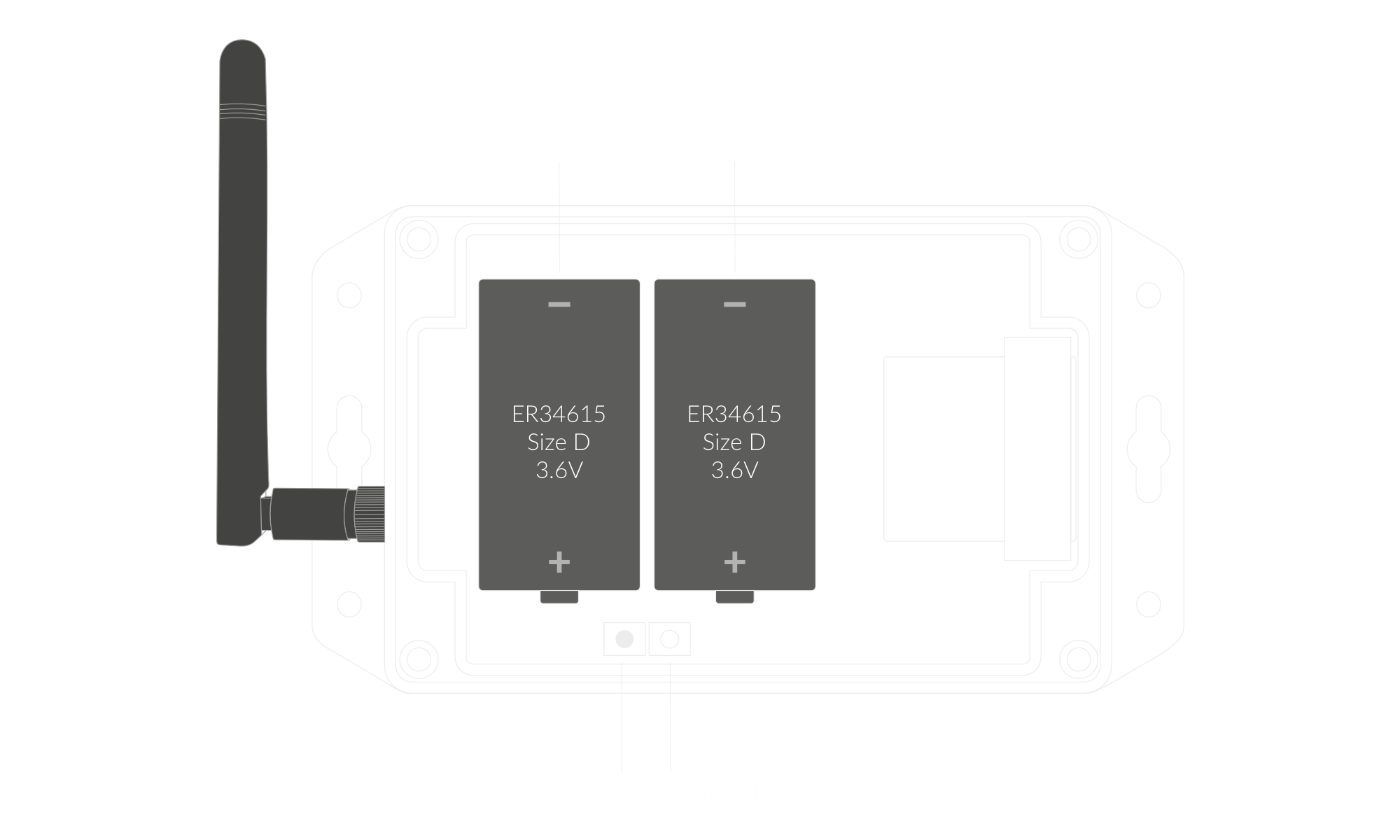
Figure 4. Reset button and LED indicator
Installation
Package Contents
- Device (without batteries).
- Antenna
- Warranty card.
Safety Precautions
Go to the Safety Precautions section to see important information on handling, disposal and maintenance.
Installation Guide
- Unscrew the device: remove 4 screws from the enclosure.
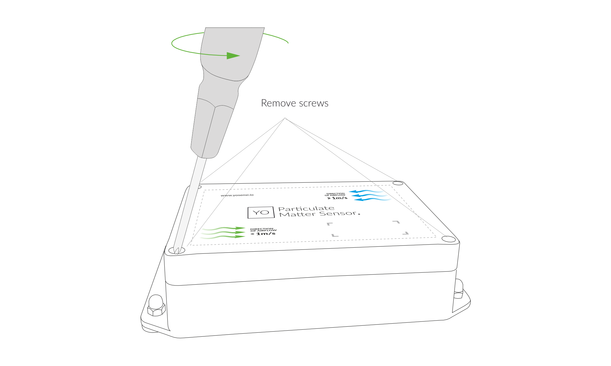
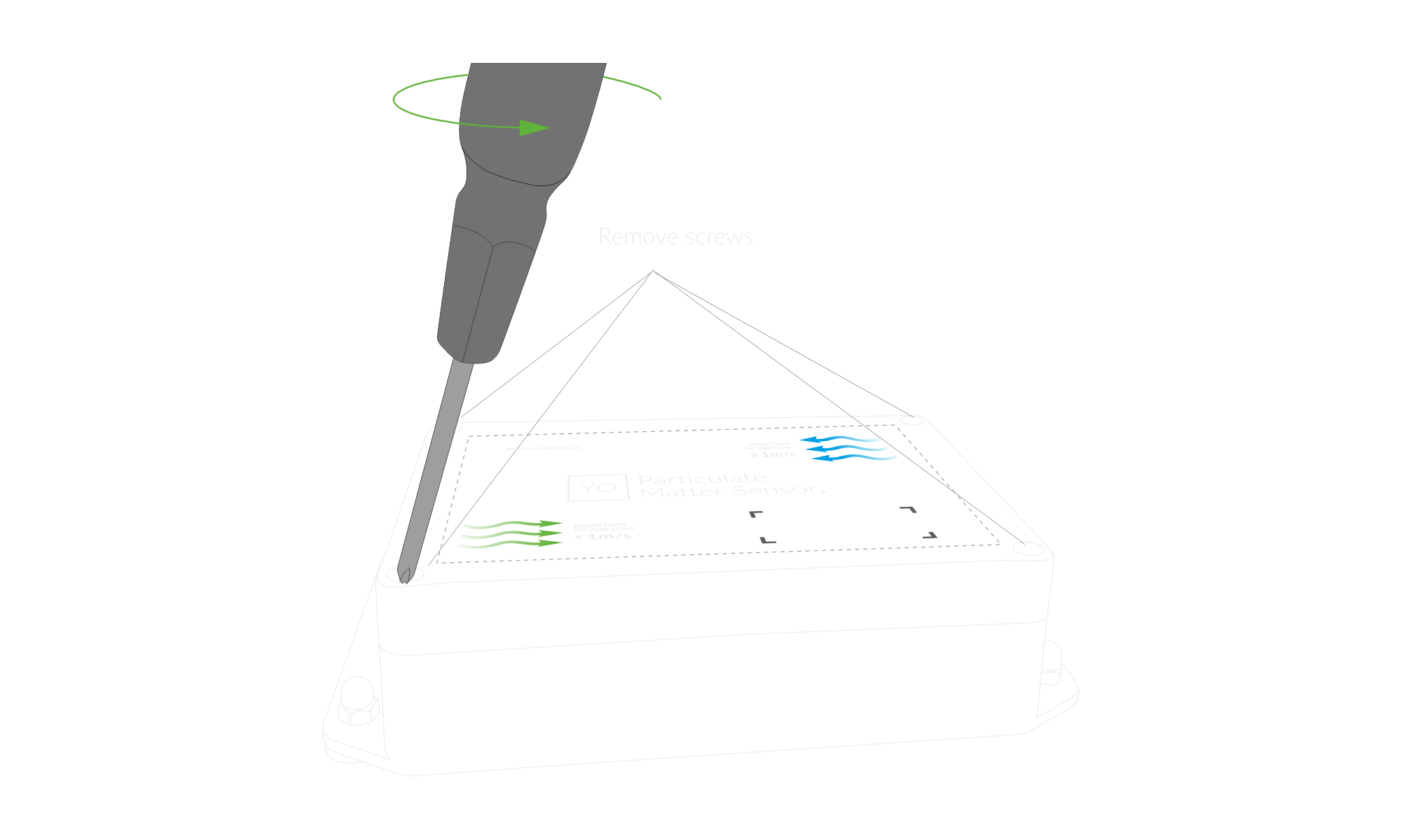
Figure 5. Unscrew the device
- Before placing the batteries, check our Mounting Guide for the correct positioning of the enclosure and PM sensor.
- Screw in the antenna and place two ER34615 (D) LiSoCL2 batteries in the device according to the polarity indicated on the battery holder.
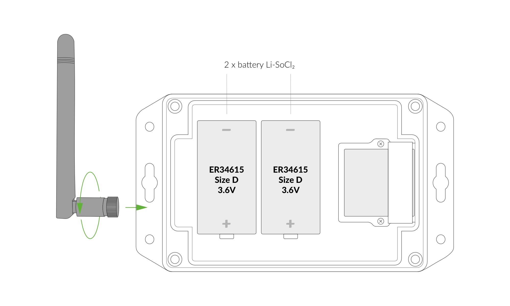
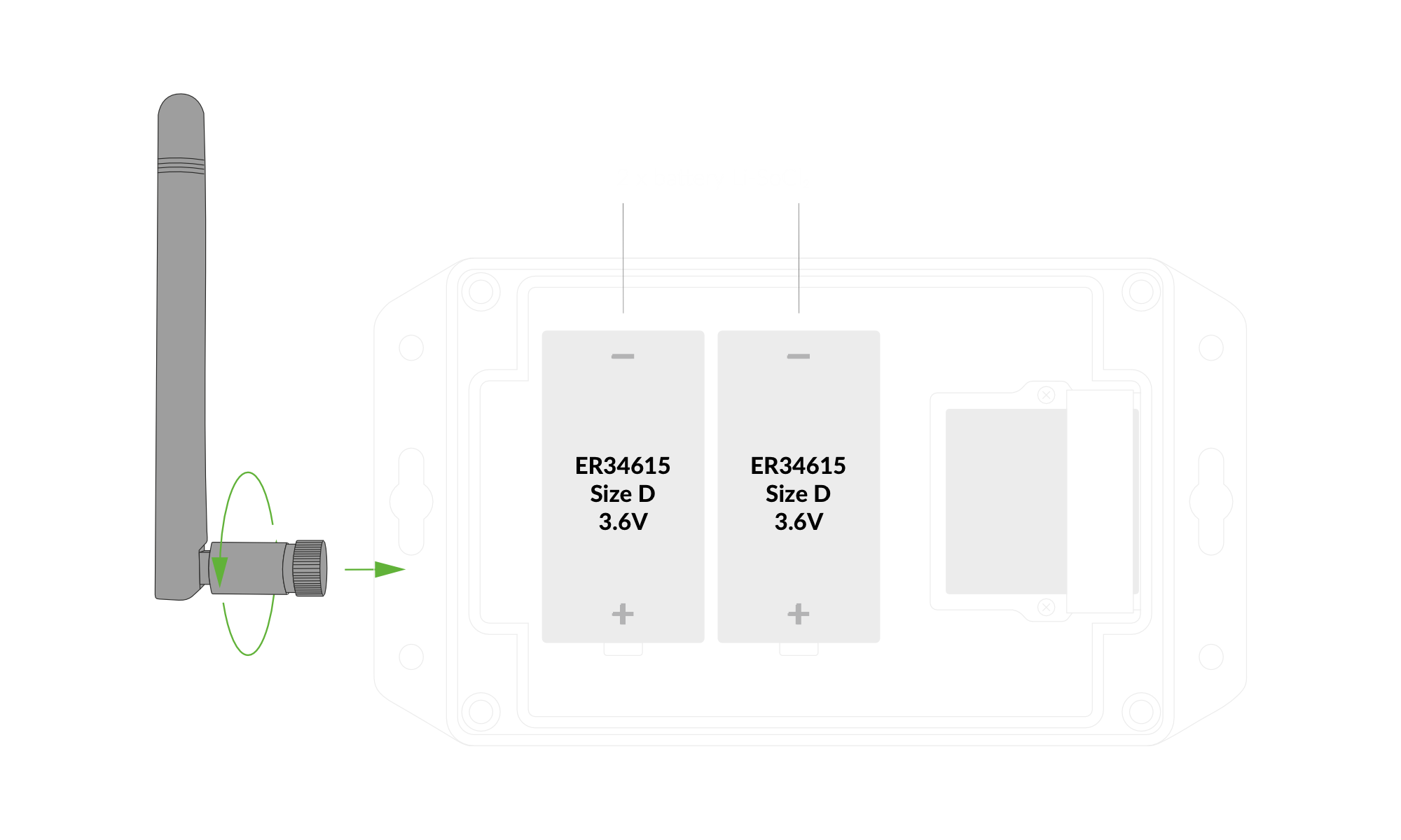
Figure 6. Battery Placement
- Screw the device back together.
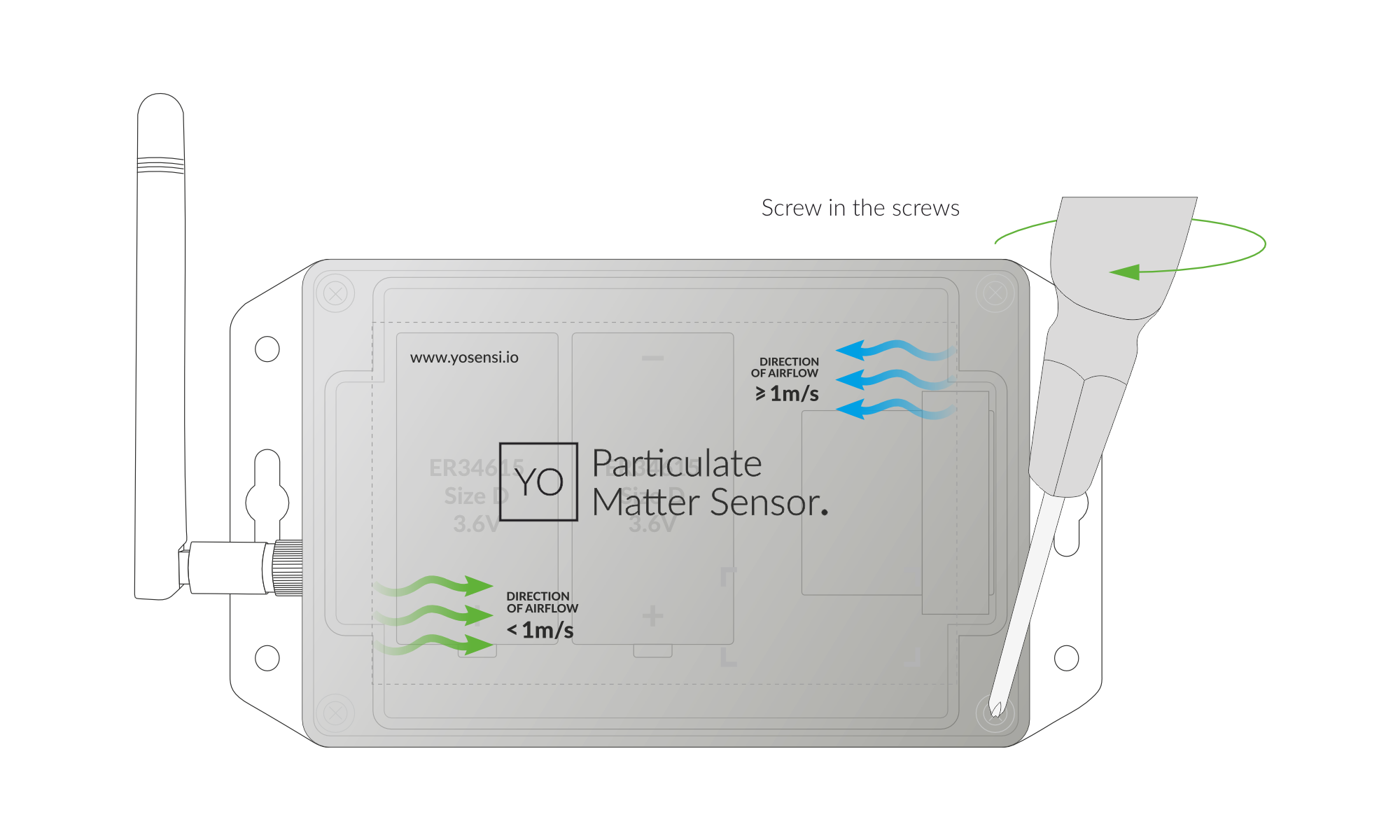
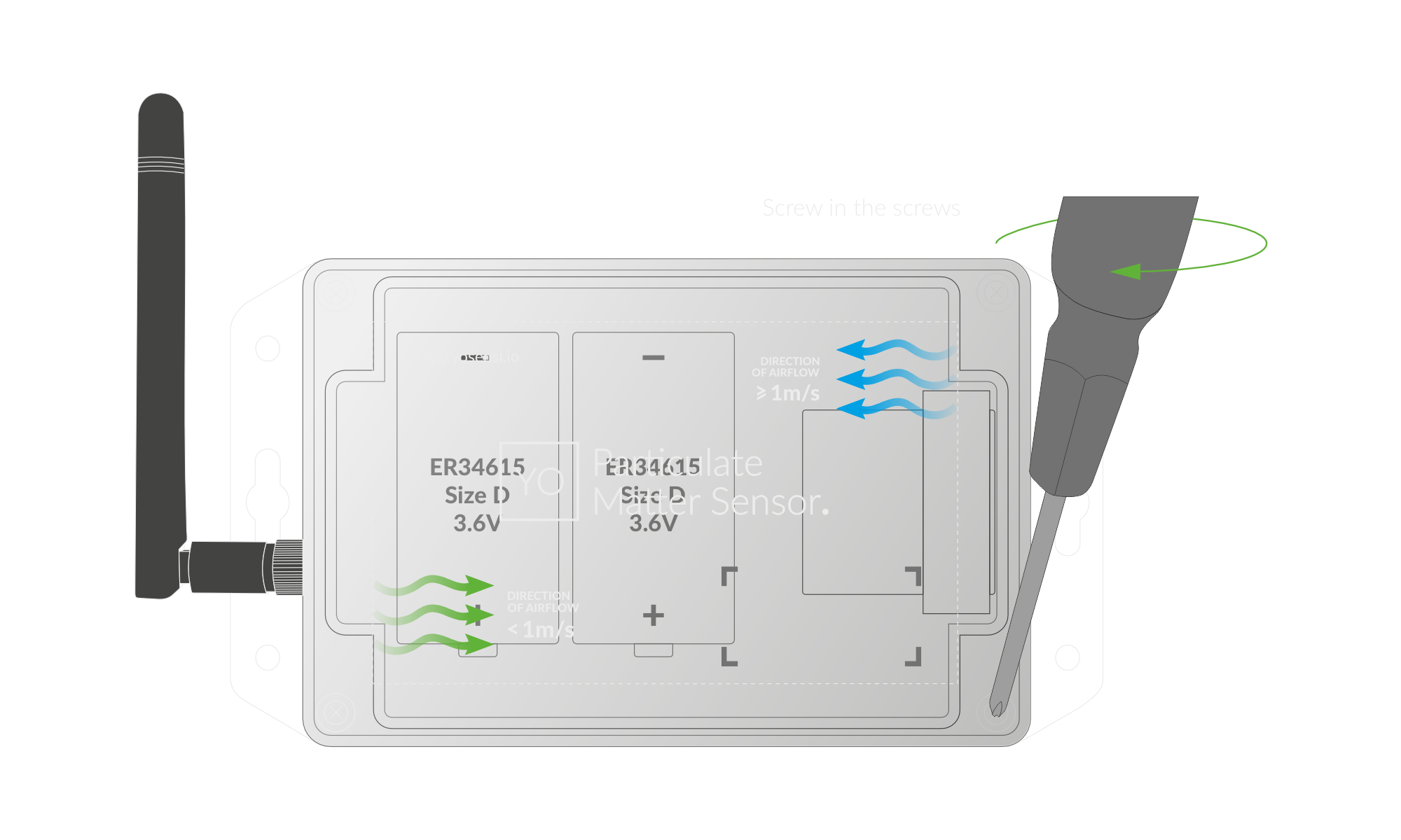
Figure 7. Screw the device back together
Mounting Guide
Airflow Guide
- Airflow exceeds 1 m/s: Align the green arrows on the top of the enclosure above the antenna.
- Airflow is below 1 m/s: Align the green arrows on the top of the enclosure above the PM sensor.
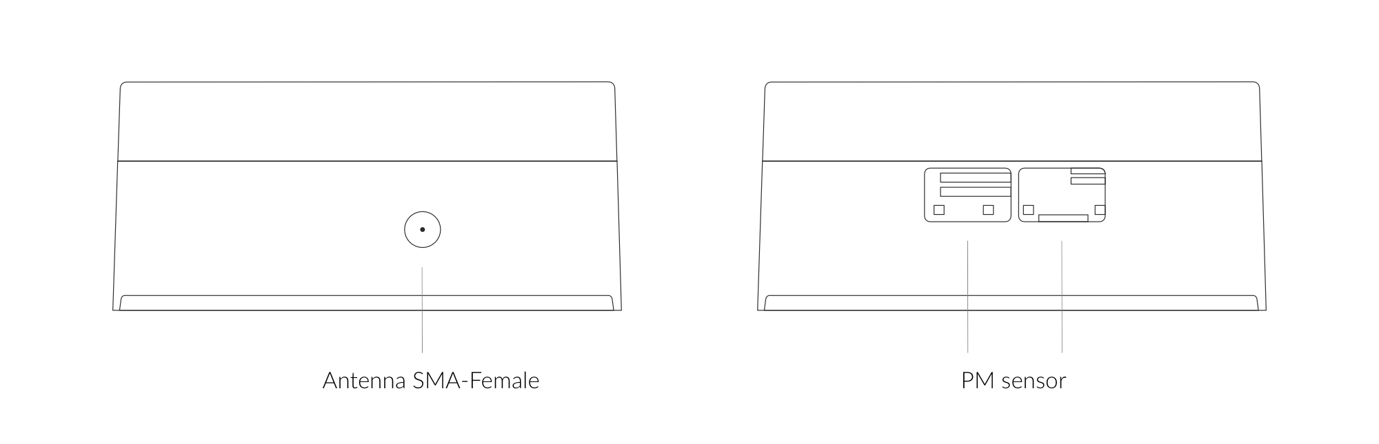
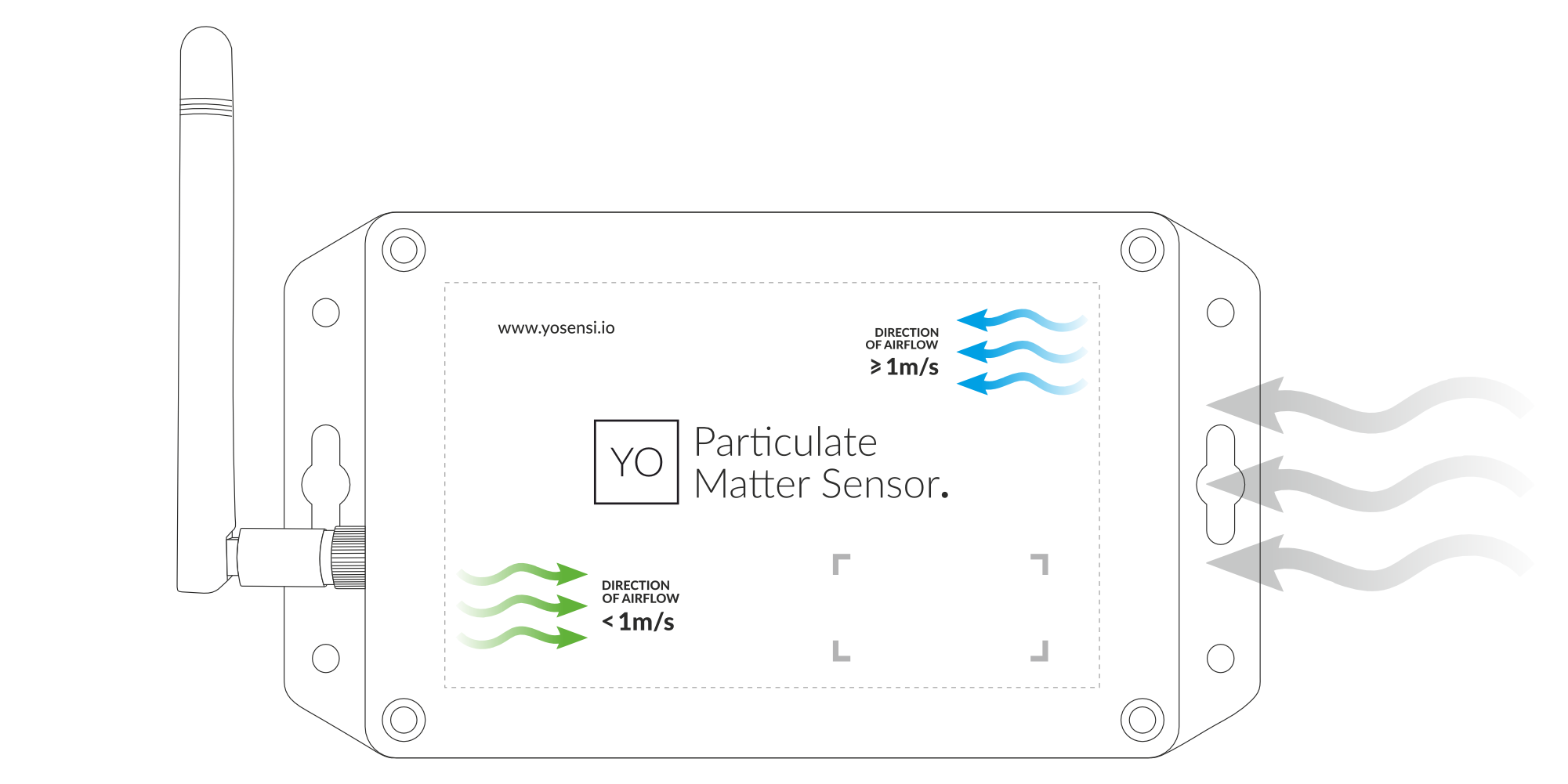
Figure 8. Antenna & PM Sensor Placement
Horizontal
The sensor comes preconfigured in the optimal position and can be mounted horizontally, following the guidelines provided in the Airflow Guide.
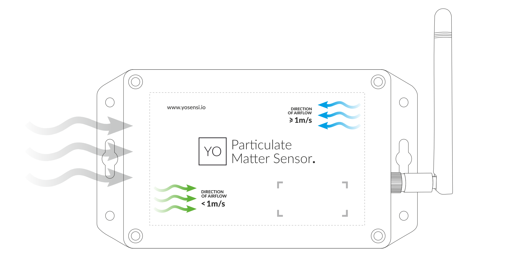
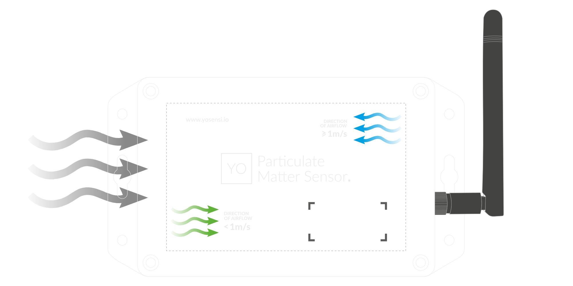
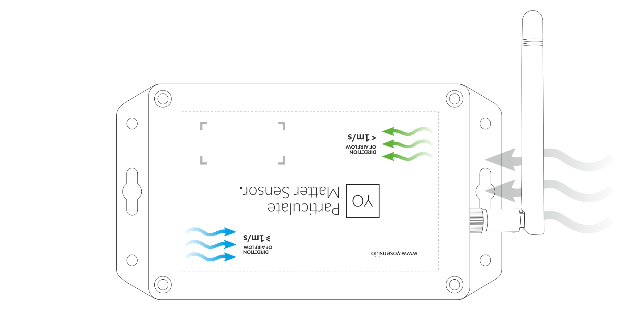
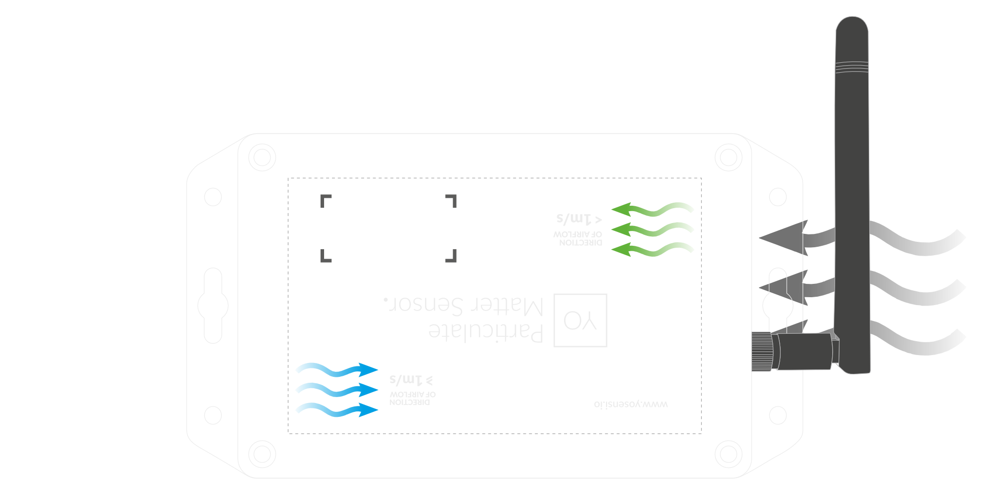
Figure 9. Horizontal Placement - Depending on the airflow speed.
Lateral
To mount the YO Particulate Matter Sensor laterally, you need to check the Airflow Guide first. Once the enclosure’s arrow points in the correct direction:
-
A. The green arrows point to the right and the airflow is less than 1 m/s, check the Guidelines for Rotating the PM Sensor.


A. Lateral Placement - Airflow < 1 m/s.
-
B. The green arrows point to the left and the airflow is more than 1 m/s, check the Guidelines for Rotating the PM Sensor.

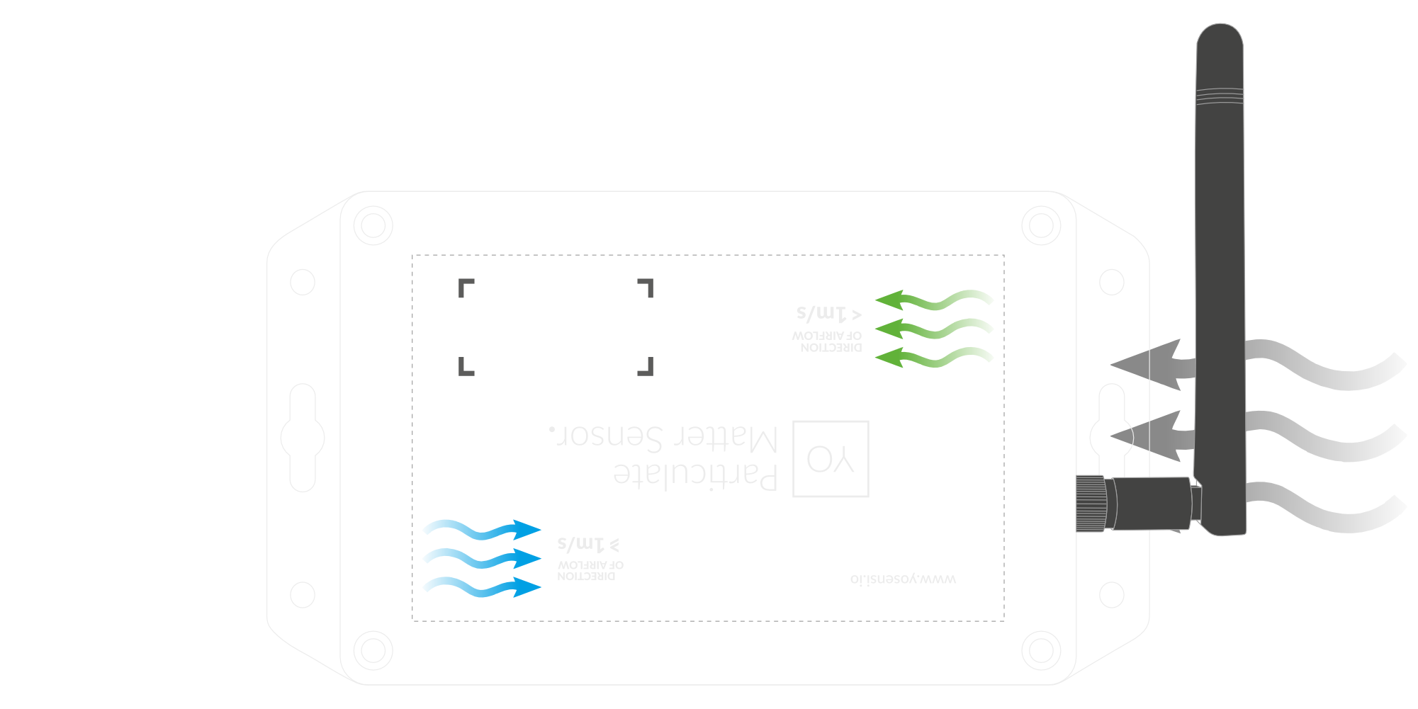
B. Lateral Placement - Airflow > 1 m/s.
-
C. The green arrows point to the right, and the airflow is less than 1 m/s, no further action is necessary.
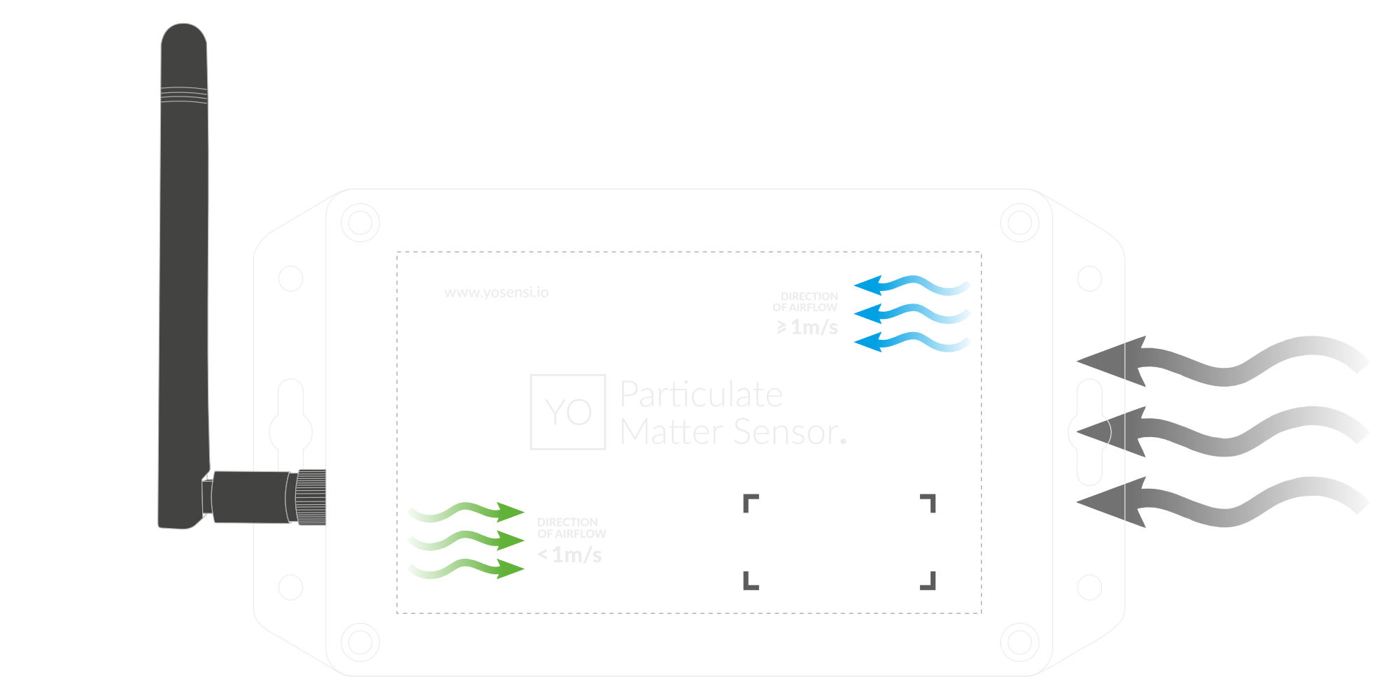
C. Lateral Placement - Airflow < 1 m/s.
-
D. The green arrows point to the left, and the airflow is more than 1 m/s, no further action is necessary.


D. Lateral Placement - Airflow > 1 m/s.
Vertical
Pay attention: The only way to mount the device vertically is by facing the sensor downward, not upward. Be mindful of the airflow speed and consult the Airflow Guide.
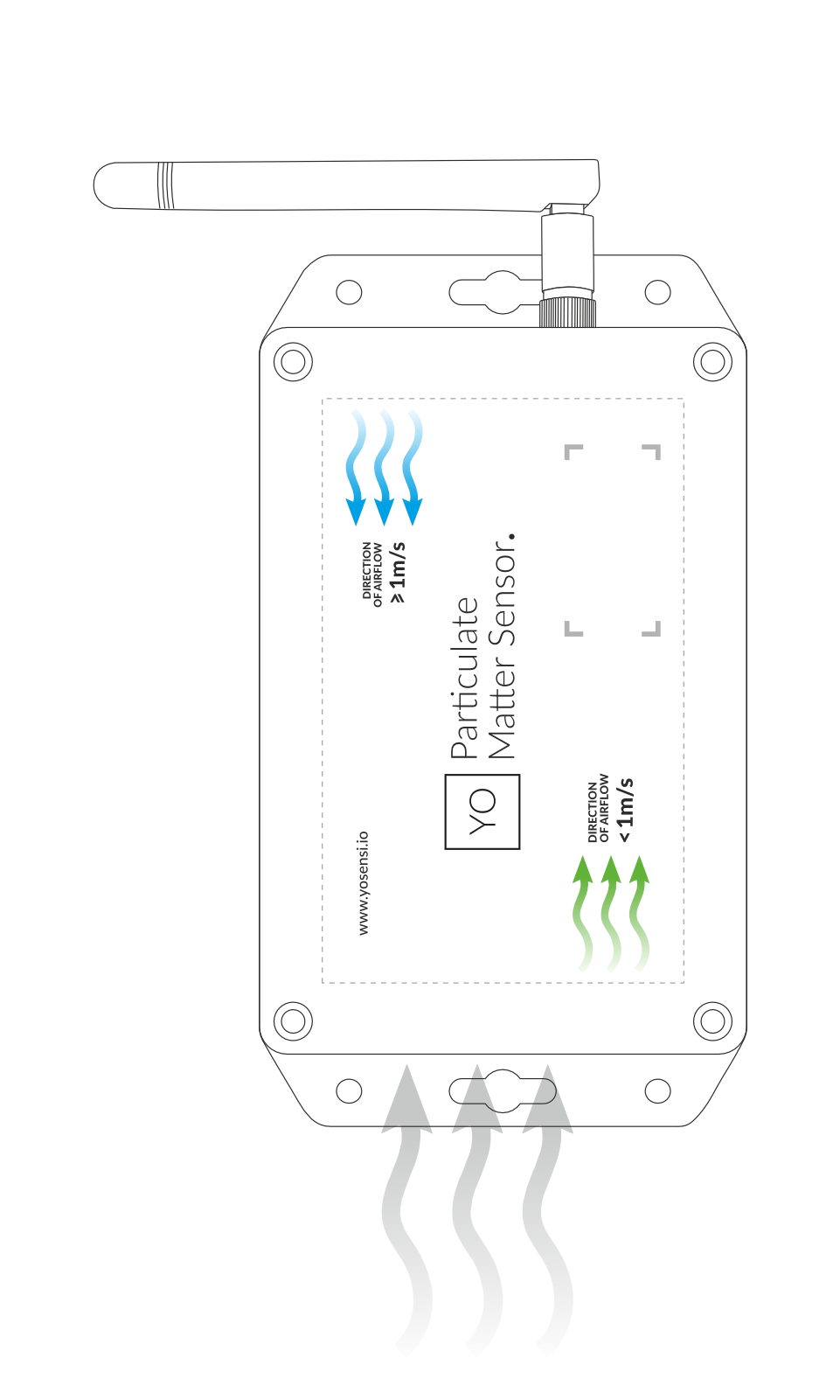 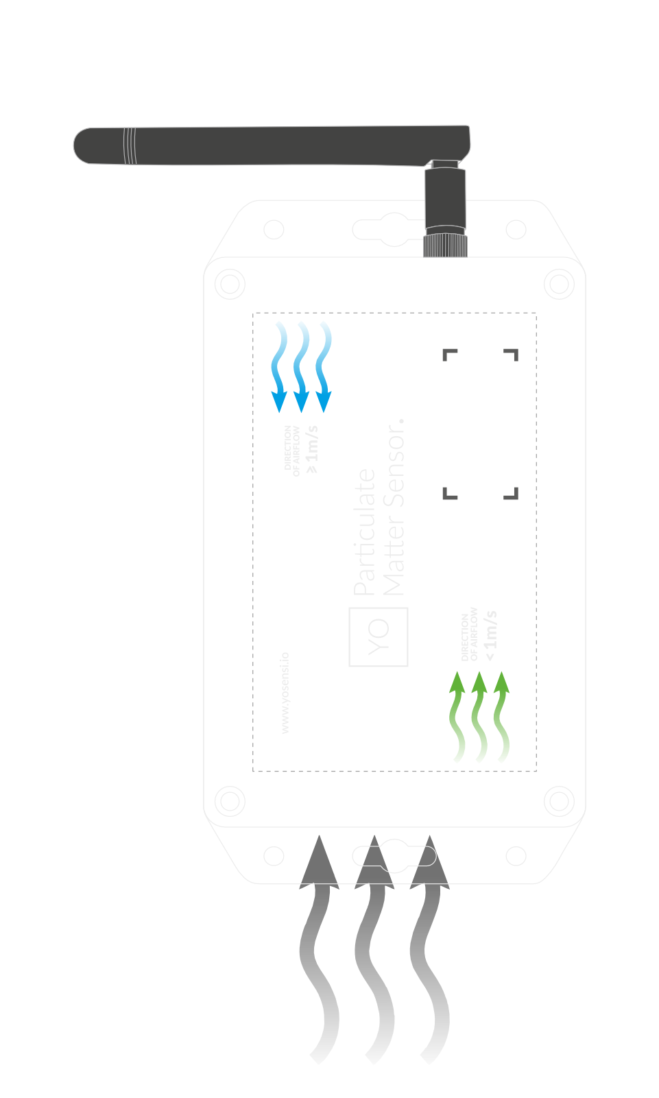 | 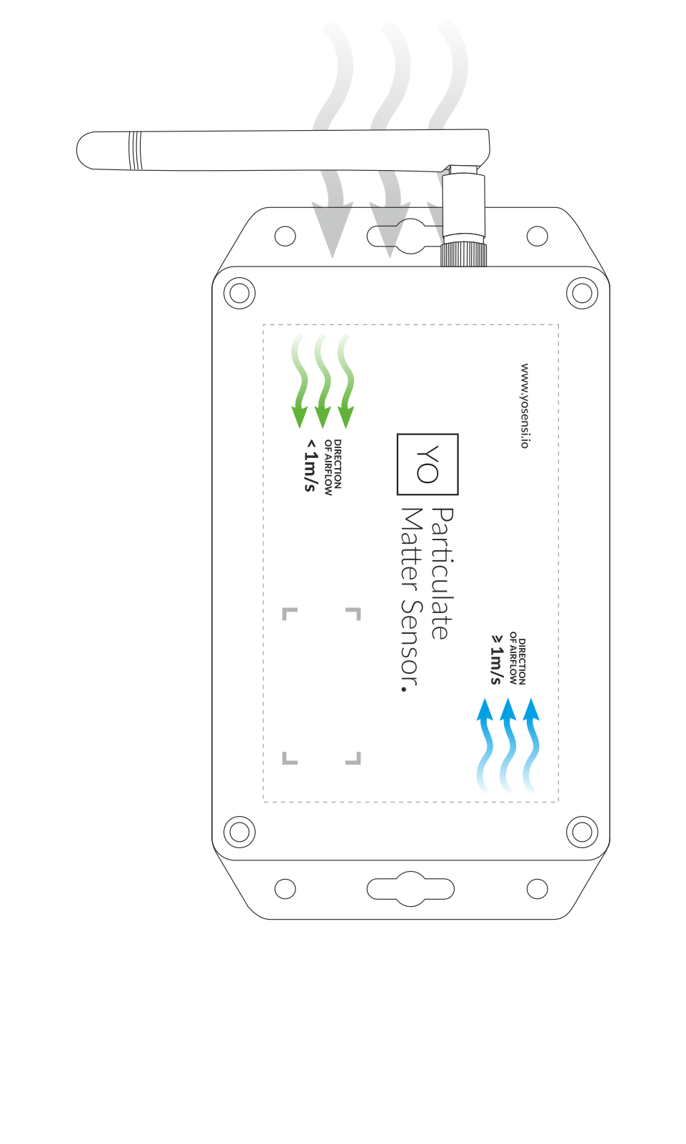 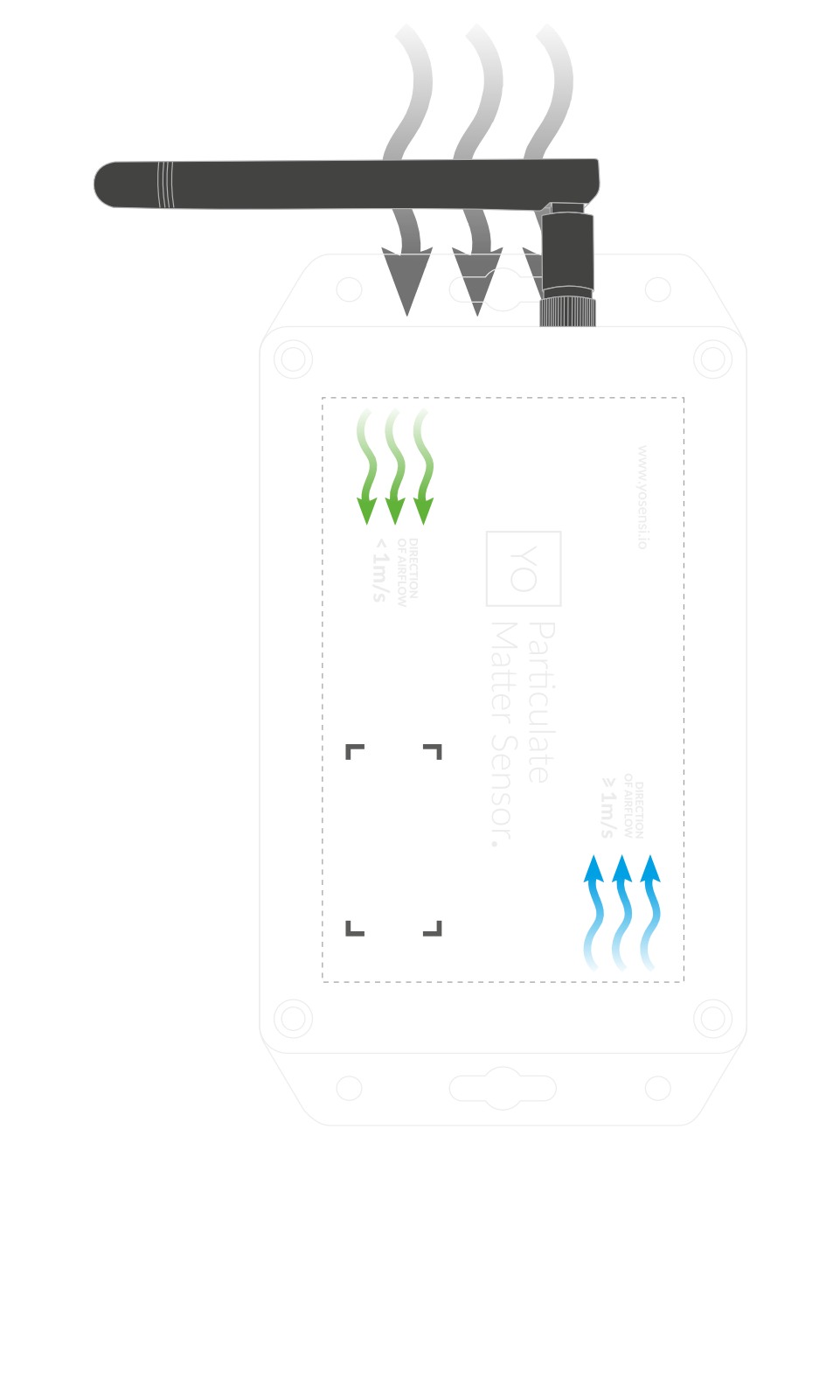 |
Figure 10. Vertical Placement | Figure 11. Vertical Placement |
Guidelines for Rotating the PM Sensor
Refer to the Mounting Guide to determine if it is necessary to rotate the PM Sensor.
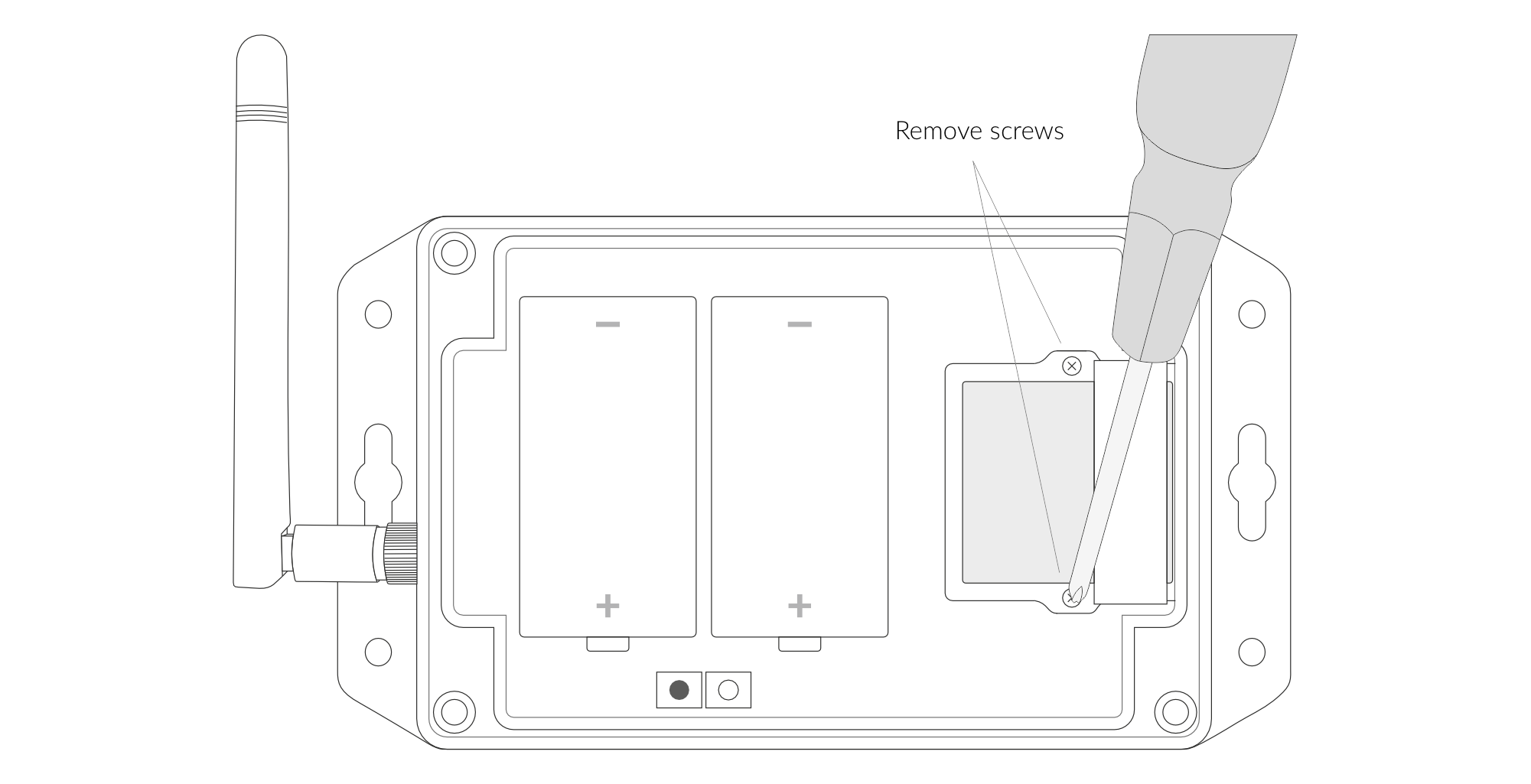
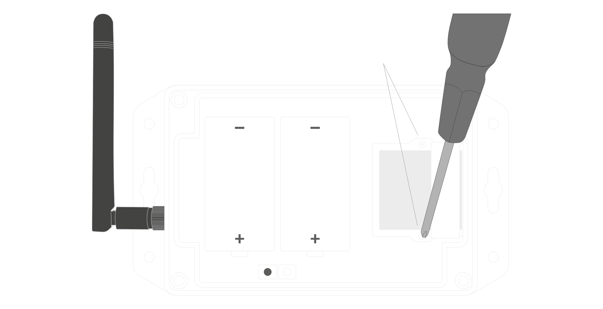
Figure 12. Remove the arm holding the PM Sensor
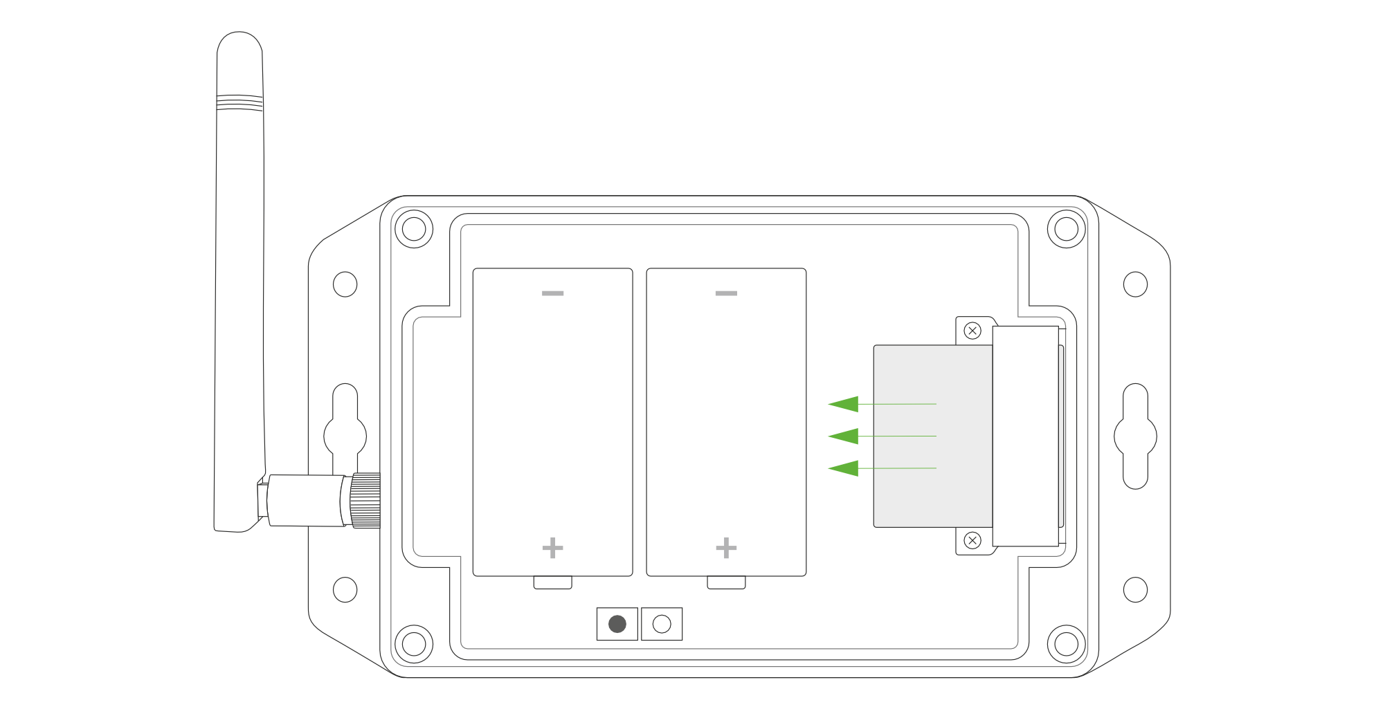
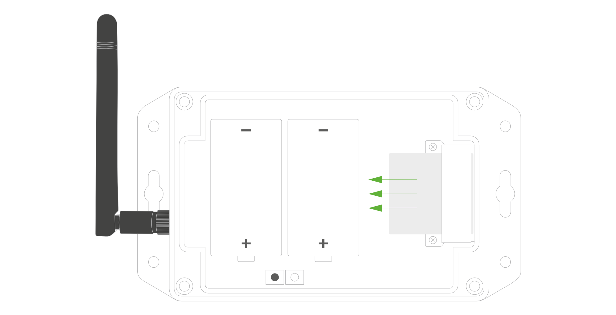
Figure 13. Pull out the PM Sensor
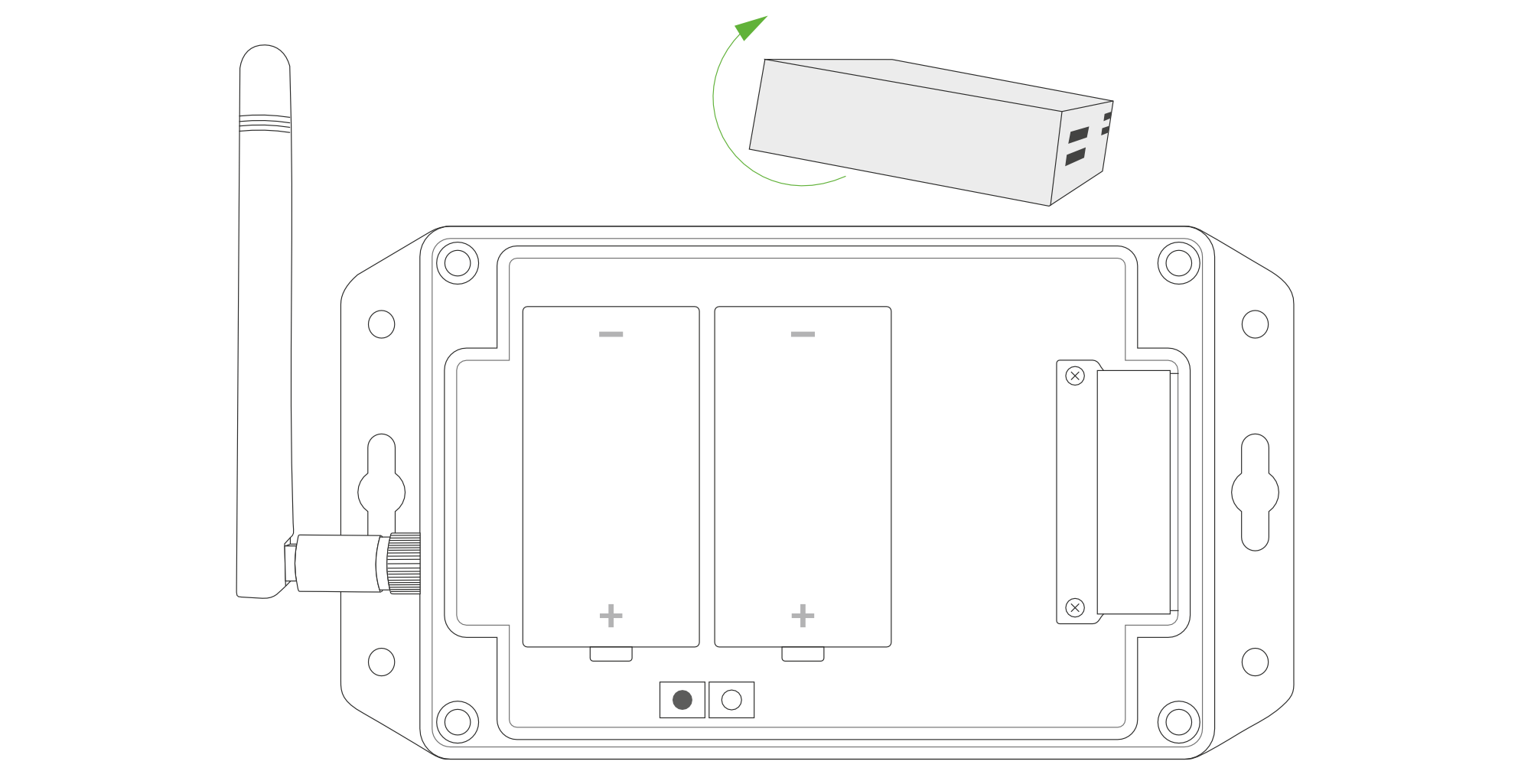
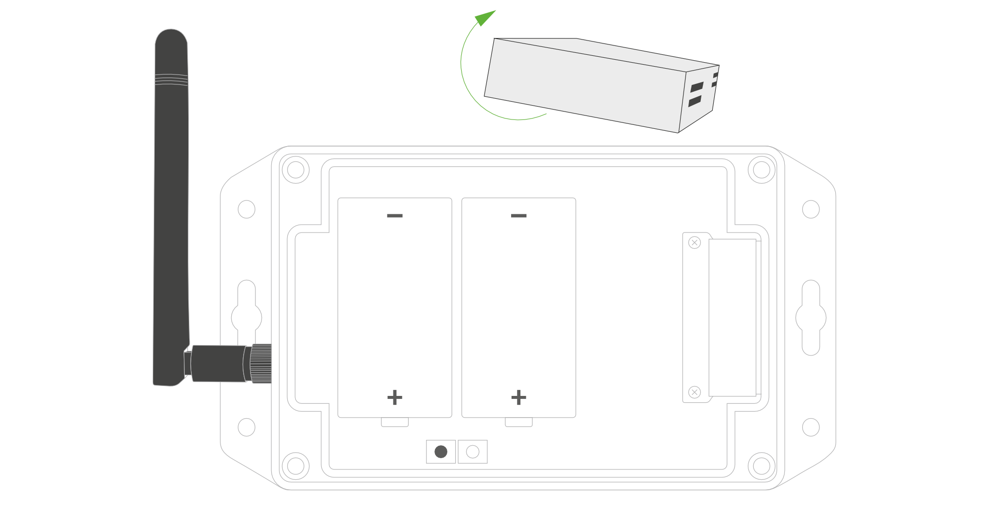
Figure 14. Rotate the PM Sensor
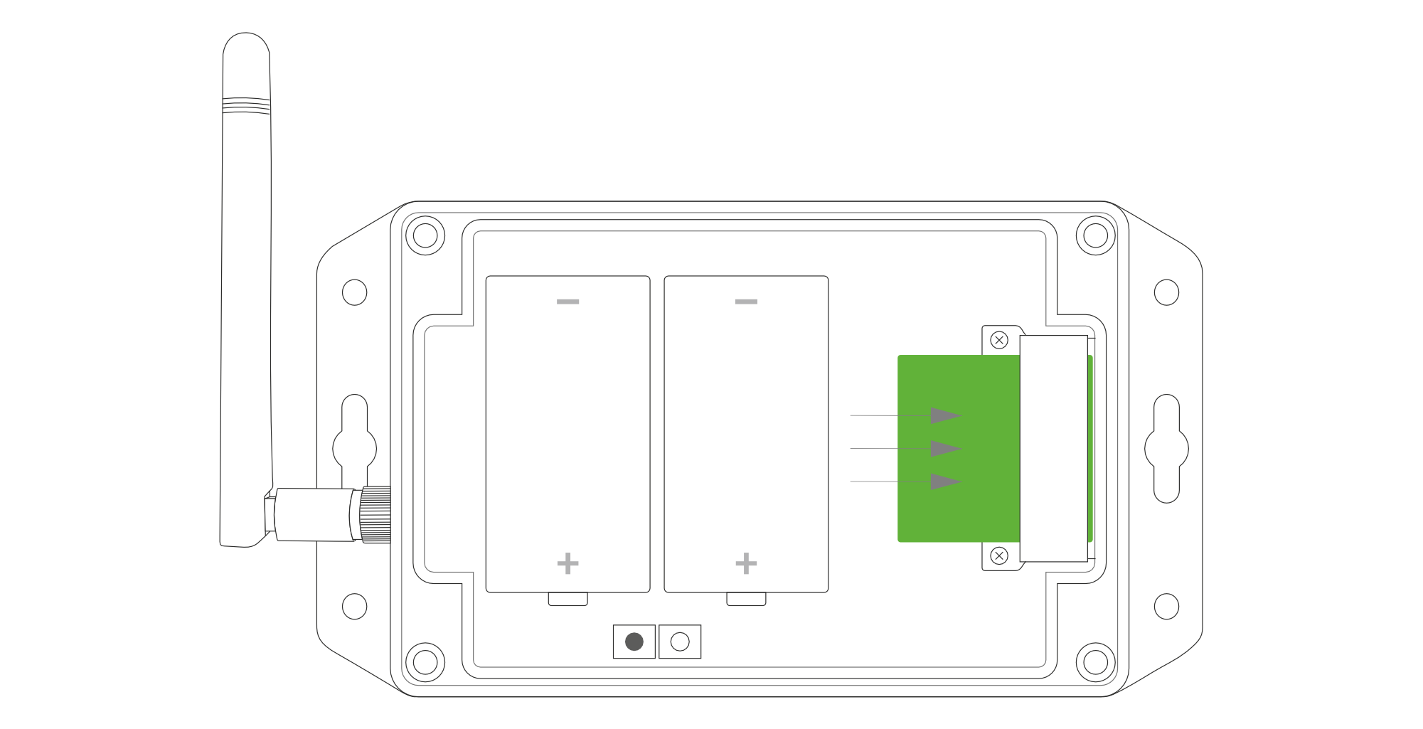
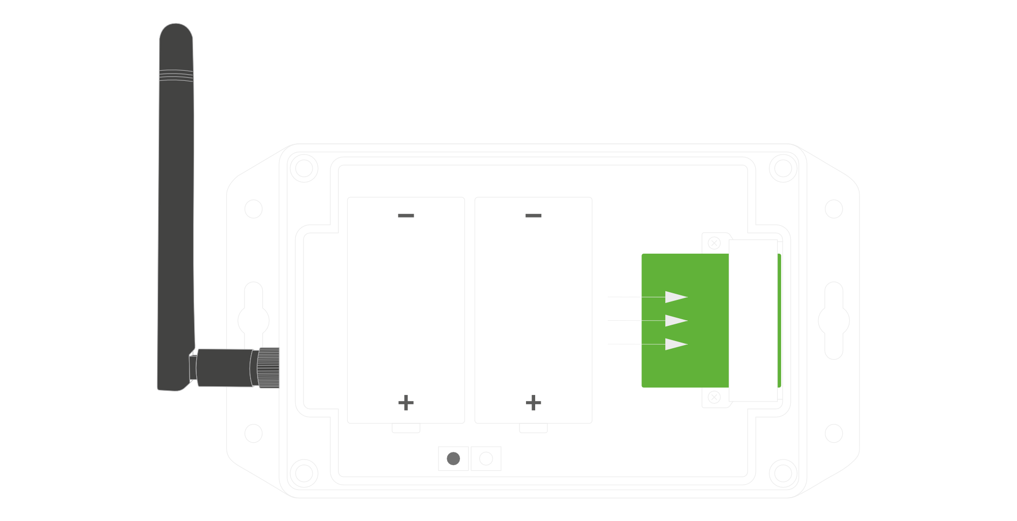
Figure 15. Put back the PM Sensor
Configuration
Configurable Parameters
A few parameters must be set before sending data to the gateway. The default firmware is configured in OTAA mode with predefined deveui, appkey (OTAA) and appskey, nwkskey (ABP).
Configuration of the device is stored in a JSON file divided into the following sections:
- info (generic, read only): information about the device,
- general (generic): general device settings,
- lorawan (generic): configuration data for LoRaWAN connection,
- ble (generic): bluetooth settings,
- device (dynamic): individual configuration for a specific device (this section’s structure differs for each device),
Sample configuration file for the YO Particulate Matter Sensor device.
{
	"info": {
		"fwver": "1.0.2",
		"devmodel": "LNPM",
		"loraradio": "SX1261",
		"blemacaddr": "0123456789ab",
		"loraregion": "EU868",
		"lorawanver": "1.0.2"
  	},
	"general": {
		"rtcstate": "disable"
	},
	"lorawan": {
		"abp": {
			"appskey": "000102030405060708090a0b0c0d0e0f",
			"devaddr": "01234567",
			"nwkskey": "0123456789abcdef0123456789abcdef"
    	},
    	"otaa": {
			"appeui": "be7a000000000688",
			"appkey": "000102030405060708090a0b0c0d0e0f",
			"deveui": "0123456789abcdef",
			"trials": 3
    	},
		"acttype": "otaa",
		"nwktype": "public",
		"subband": 1,
		"retrycnt": 3,
  	},
	"ble": {
		"power": 0,
		"interval": 1600
  	},
	"device": {
		"measinterval": 600,
		"pmxstartuptime": 30,
		"pmxsamplestoavg": 30
  	}
}
OTAA & ABP
| OTAA | ABP |
|---|---|
| Device EUI | Device Address |
| Application EUI | Network Session Key |
| Application Key | Application Session Key |
| Number of Trials |
Generic Parameters
Click here to see the generic parameters for Yosensi devices.
Parameters Description
| Name | Description | Possible Values | Default Value | Read/Write |
|---|---|---|---|---|
| measinterval | Measuring and sending interval LoRa [s] | 601-999999 | 3600 | R/W |
| pmxstartuptime | Time before first measurement [s] | 8-60 | 30 | R/W |
| pmxsamplestoavg | Averaging a defined amount of samples into a measurement | 1-60 | 30 | R/W |
| ||||
Parameters description
- rtcstate: used for enabling/disabling the real-time clock (RTC) inside the device. The RTC is used for timestamping the measurements.
- nwktype: used for setting the device in public or private network type.
- acttype: used for setting the device in ABP or OTAA mode.
- deveui, … , appskey: predefined addresses and keys, these parameters are generated using multiple IDs specific to the particular MCU and are unique for each device. They can be changed if needed.
- interval: determines the interval of sending broadcast packets, used to connect to every BLE receiver around the device.
- subband: used for setting the communication frequency sub-band in LoRaWAN.
- retrycnt: number of retries to send a LoRa packet if the acknowledgement is not received from the LoRaWAN server.
- measinterval: measurement interval [s] between sending LoRa packets.
- pmxstartuptime: time [s] before first measurement
- pmxsamplestoavg: averaging a defined amount of samples into a measurement
Downlink message
You can remotely adjust certain parameters by sending a downlink message through our platform. Simply navigate to the "COMMANDS" section for the selected device.
Update Measurement Interval
It is possible to change the measurement interval (measinterval) by using downlink. Information about changing the parameter will be sent from the server via the gateway.
Example of Downlink Message:
- Prefix:
0x03 - Measurement Index:
0x00 - Data (up to 4 bytes in hex):
0x0258
Sample Downlink: 0x03000258 - Sets a measurement interval of 600 seconds (10 minutes).
Update Time Before First Measurement
It is possible to change the Time before the first measurement (pmxstartuptime) by using downlink.
Example of Downlink Message:
- Prefix:
0x03 - Measurement Index:
0x01 - Data (up to 4 bytes in hex):
0x000a
Sample Downlink: 0x0301000a - Sets the time before first measurement to 10s.
Update Defined Average Number of Sample in a Measurement
It is possible to change the defined average number of samples in a measurement (pmxsamplestoavg) by using downlink.
Example of Downlink Message:
- Prefix:
0x03 - Measurement Index:
0x02 - Data (up to 4 bytes in hex):
0x000f
Sample Downlink: 0x0302000f - Sets the defined average number of samples in a measurement to 15.
Click here to see how to connect a node using the Yosensi Management Platform.
See how to configure a node in Yosensi Management Platform
Check how to adopt and configure a node via the Yosensi App.
Take a look at the list of frequency plans used in Yosensi.
This datasheet describes the payload protocol developed by Yosensi for communicating with our devices.
Payload Decoder
If you want to connect to your own server, it is necessary to decode the specific payload for each device. To accomplish this, a payload decoder is required, which can be downloaded using the following link: Payload decoder. You can also use our integrated Payload Decoder here. Extended documentation of the protocol can be found in the Payload description on our website.