YO Pure Pro
Overview
Description
The YO Pure Pro is an advanced indoor environmental monitoring device designed to measure a wide range of air quality parameters, including particulate matter (PM2.5, PM4, PM10), carbon monoxide (CO), carbon dioxide (CO₂), and total volatile organic compounds (TVOC). It also features sensors for atmospheric pressure, illumination, temperature, humidity, and noise levels. For added versatility, the device can be customized to replace the default CO sensor with options for O₃, ETOH, H₂S, SO₂, or NO₂ measurement, making it an adaptable solution for diverse environmental monitoring needs.


Figure 1. Device top view
Device sticker placed on the bottom of the device enclosure contains information about model, version, LoRaWAN region and 3 parameters important in case of device identification and configuration:
- DEV EUI: 64-bit unique device identifier in a LoRaWAN network,
- DEV ADDR: address required to connect via ABP activation type to LoRaWAN,
- BLE MAC: Bluetooth physical address.


Figure 2. Device sticker
Features
- LoRaWAN Technology: Available in multiple versions with LoRa radio configured for various regions and ISM frequency bands (e.g., EU868, US915, AU915), it is compatible with both private and public LoRaWAN networks and supports connections via ABP (Activation by Personalization) or OTAA (Over-The-Air Activation).
- Bluetooth Low Energy (BLE): Enables easy configuration through a user-friendly JSON data exchange format, supports firmware updates via OTA (Over-the-Air), and boasts very low energy consumption.
- Temperature and Relative Humidity: Measures temperature and relative humidity within the device enclosure, providing valuable insights into the surrounding environment.
- PM2.5, PM4, and PM10: Provides detailed information about the concentration of particulate matter in diameters equal to or less than 2.5 μm, 4 μm, and 10 μm, offering valuable insights into air quality and surrounding pollution levels.
- CO: Continuously monitors carbon monoxide concentration, an odorless yet critical indoor environmental parameter, to ensure safe levels and inform appropriate ventilation in indoor spaces, protecting human health.
- CO2: Tracks carbon dioxide levels, an essential indoor environmental parameter, to prevent adverse effects on human health such as poor concentration, increased heart rate, and reduced attention due to elevated CO2 concentrations.
- TVOC: Measures the concentration of total volatile organic compounds, an important indicator of indoor air quality and hygiene, to ensure a healthy and comfortable environment.
- Atmospheric Pressure: Tracks changes in pressure, providing insights into how fluctuations may impact human mood and overall well-being.
- Illuminance: Measures light intensity, helping to determine if the room has an adequate level of lighting for comfort and productivity.
- Sound Pressure Level: Measures the noise intensity in a room, enabling monitoring of the building's acoustic environment.
- Yosensi Management Platform: Provides a web tool for device configuration, firmware updates, and infrastructure management. Enables comprehensive monitoring of transmitted data and easy device management.
- Yosensi Mobile App: Effortlessly manage devices with features to register new ones, configure settings, perform firmware updates, view/send logs, and test LoRaWAN connectivity. Learn more in our detailed Yosensi App blog post.
Specifications
Physical
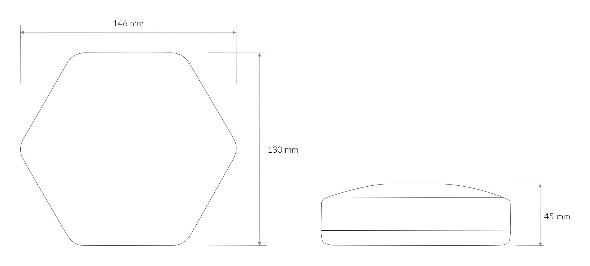
Figure 3. Dimensions of the device
Device
| Attribute | Description |
|---|---|
| Dimensions | Height: 45 mm Width: 130 mm Depth: 146 mm |
| Colour | White |
| Mounting method | Horizontal Vertical (can be screwed to the wall) |
| Enclosure material | ABS |
| Level of protection | IP40 |
| Weight | 260 g (without batteries) |
Operating Conditions
| Attribute | Description |
|---|---|
| Temperature | 0°C to 70°C |
| Humidity | 0 to 90% |
| Placement | Indoor use |
| Power supply | USB-C 5 V DC 6 to 30 V DC 5 to 21 V AC 2x backup battery Li-Ion 18650 (2x 3,6 V DC) |
| Power consumption | Maximum: 1.1 A DC (12 V DC) |
Measured Values
| Parameter | Measurement range | Accuracy |
|---|---|---|
| PM2.5 pre-calibrated | 0 to 1000 μg/m3 1 | ±10 μg/m3 at 25°C |
| PM4 | 0 to 1000 μg/m3 | ±25 μg/m3 at 25°C |
| PM10 | 0 to 1000 μg/m3 | ±25 μg/m3 at 25°C |
| CO (default) | 0 to 1000 ppm 2 | ±15% of reading |
| SO2 (optional) | 0 to 20 ppm | ±15% of reading |
| ETOH (optional) | 0 to 800 ppm | ±15% of reading |
| H2S (optional) | 0 to 10 ppm | ±15% of reading |
| NO2 (optional) | 0 to 20 ppm | ±15% of reading |
| O3 (optional) | 0 to 5 ppm | ±15% of reading |
| CO2 | 0 to 40.000 ppm 3 | ±(40 ppm + 5%) 400 ppm to 5000 ppm |
| Total volatile organic compounds (TVOC) pre-calibrated | 0 to 20 mg/m3 | ±15% of reading |
| Atmospheric pressure | 10 to 1200 hPa | ±1.5 hPa at 25°C |
| Illuminance | 0 to 120 klx | ±10% at 25°C |
| Sound Pressure Level | 45 to 110 dB SPL | -42 dBV/Pa |
| Relative humidity | 0% to 100% | ±2% (20% to 80%) |
| Temperature | -40°C to 125°C | ±0.2°C (5°C to 60°C) |
| ||
Controls and Indicators
LED Status Indicator
YO Pure Pro communicates its current behaviour to the user by RGBW LED placed on the side.
Diode statuses interpretation
| Behavior | Colour | Status |
|---|---|---|
| Single flash | Green | General: device is working correctly (power and memory). |
| Single flash | Red | General: device is working incorrectly (power and memory). LoRaWAN communication: failed to receive an acknowledgement from LoRaWAN Server within specified timeout. |
| Single flash | White | LoRaWAN communication: LoRaWAN frame sent / confirmation from LoRaWAN Server after receiving the frame. |
| Slow flashing | Blue | BLE communication: connection to the device via BLE (configuration). |
| Rapid flashing | Blue | LoRaWAN communication: connecting to LoRaWAN network. |
| Constant | Orange | General: battery charging process in progress. |
Buttons
The YO Pure Pro has a button for resetting the device. Figure 4 shows its placement. To reboot the device, press the reset button for a moment.


Figure 4. Reset button
Installation
Package Contents
- Device (without batteries).
- Mounting bracket.
- Battery lock.
- External power supply connector.
- Warranty card.
Safety Precautions
Go to the Safety Precautions section to see important information on handling, disposal and maintenance.
Installation Guide
Powering the device
The device can be powered via a USB-C connector, an external power supply, or Li-Ion 18650 batteries.
- USB-C connector 5 V DC
Plug the USB-C cable into the socket on the enclosure. If the LED indicating the status of the device ashes blue, then the device is successfully connected to the power supply.
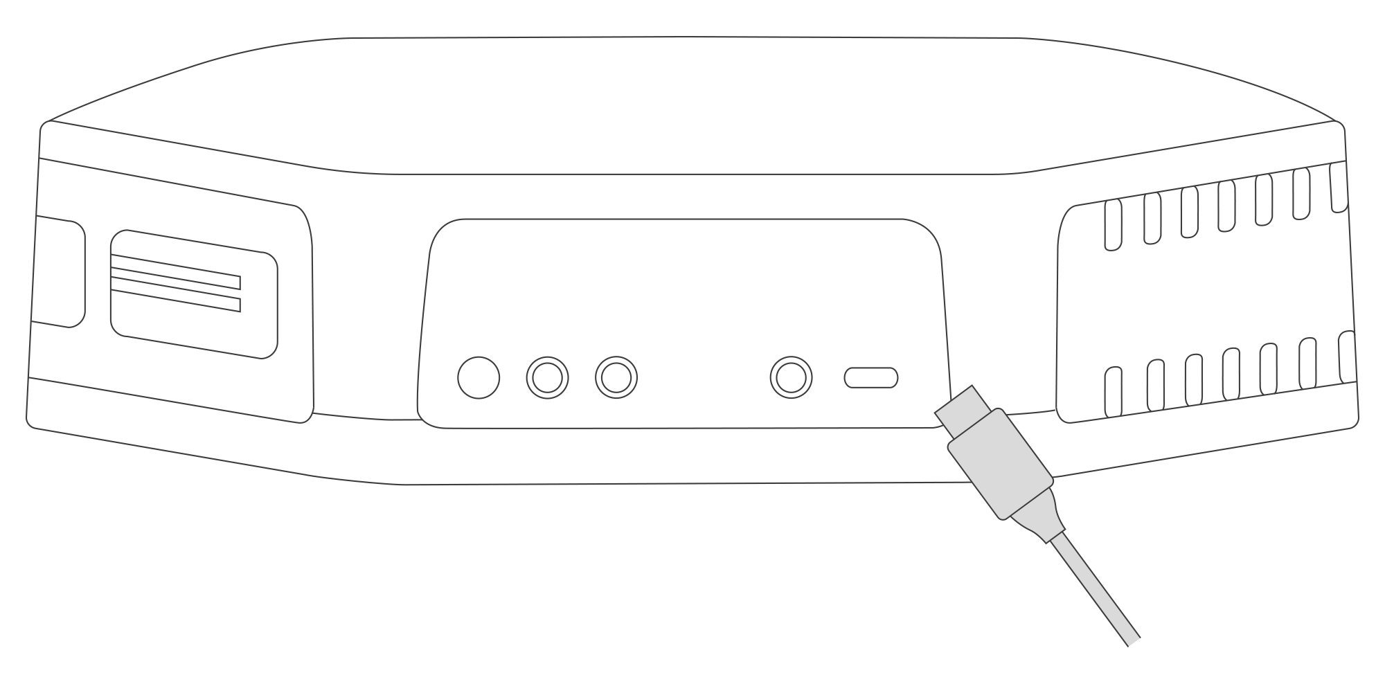
Figure 5. Connecting USB-C cable to the device
- Power supply 6-30 V DC or 5-21 V AC
Screw the external power supply wires into the plug of the connector located at the back of the device. Next, insert the connector into the socket located at the bottom of the device. If the device status LED ashes blue, then the device is successfully connected to the power supply.
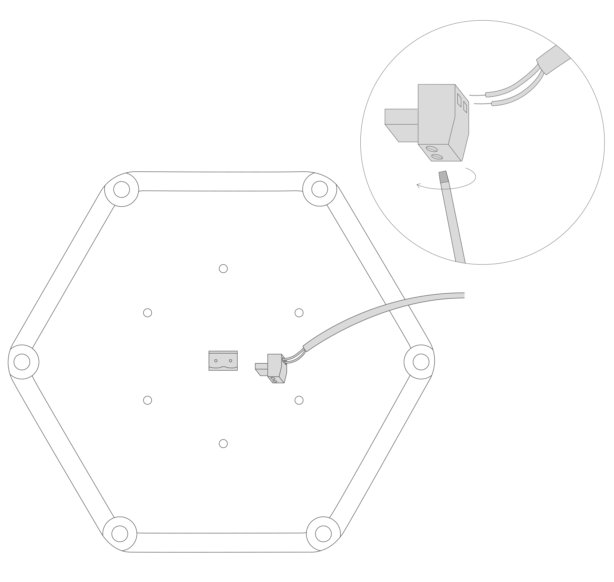
Figure 6. Connecting the power supply to the device
- Backup batteries Li-Ion 18650
Remove the three screws located on the bottom of the device’s enclosure (3 out of 6 places marked with +) to remove the top of the enclosure. Remove the battery lock and insert two Li-Ion 18650 batteries.
IMPORTANT! Align the batteries with the correct +/- polarity before re-inserting the battery lock. When the batteries are inserted correctly, the charging process begins, and the battery charging LED illuminates orange.
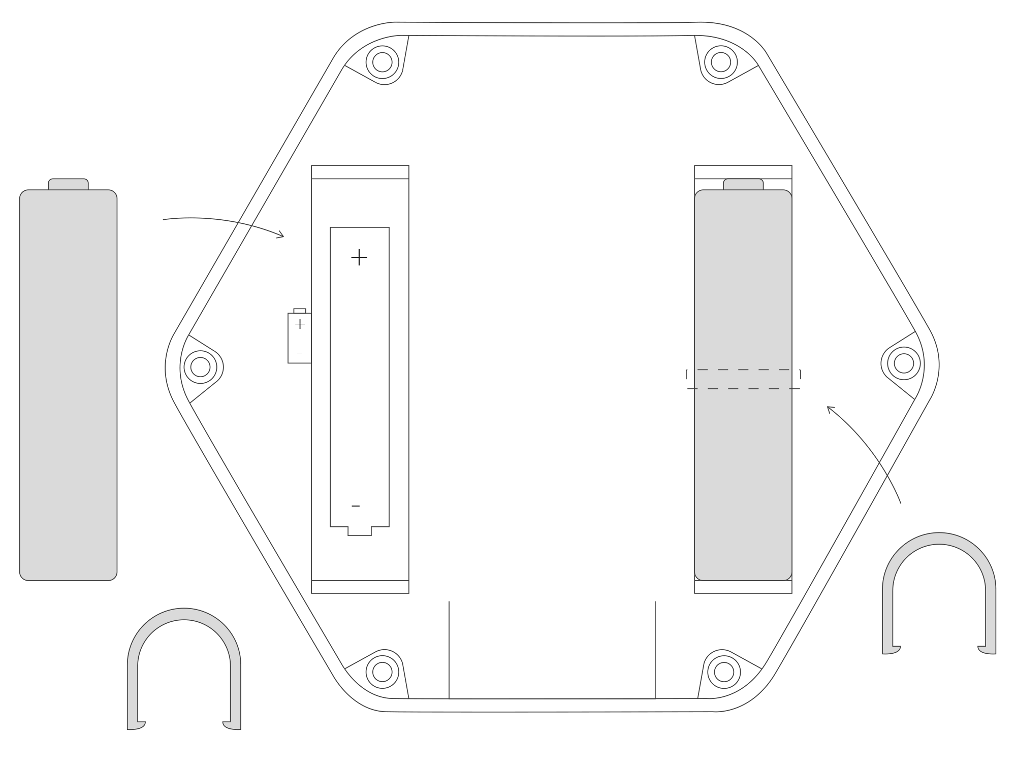
Figure 7. Inserting two batteries into the device
Installing the device
There are 3 ways to install the device.
- Place on a desk. Install the rubber feet (installed by default) and connect the power supply.
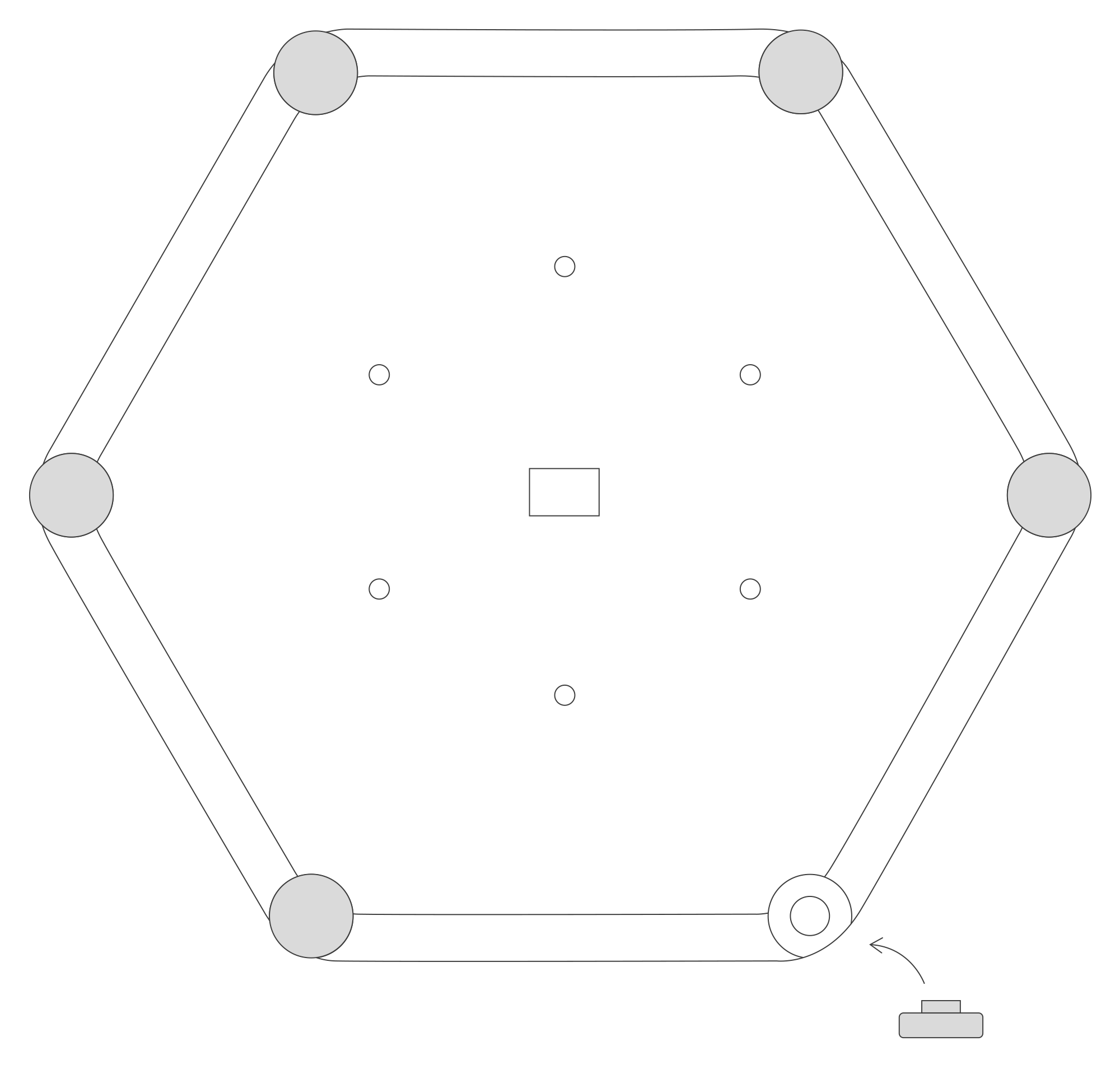
Figure 8. Installation of the rubber feet for a desk placement
-
Mount on a wall.
- A. Screw the mounting nuts into the enclosure.
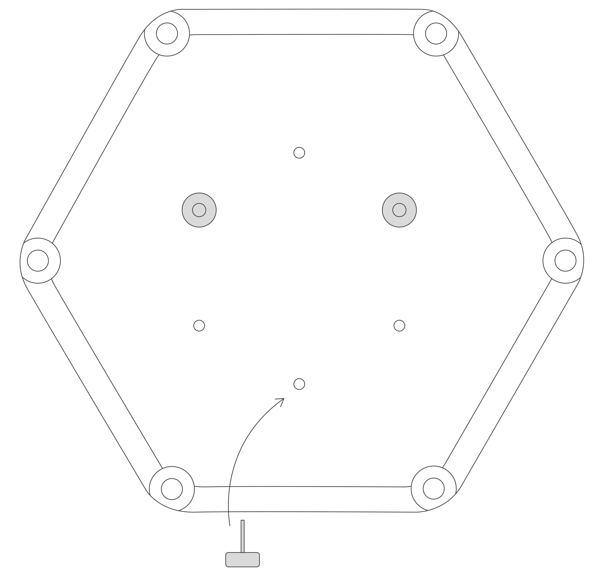
Figure 9. Screw the mounting nuts into the device for a wall installation
- B. Install the mounting bracket on the wall using screws. Screw the bracket to the wall using your preferred mounting holes.
- C. When using a 6-30 V DC or 5-21 V AC power supply, the centre plastic circle labelled PUSH must be snapped out of the mounting bracket before installation. Next, route the cable through the centre hole of the bracket.
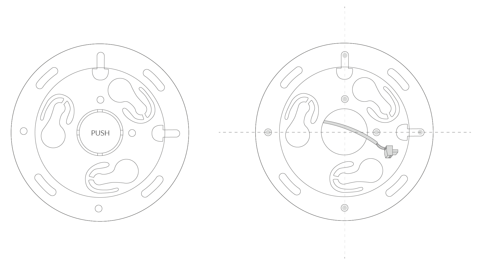
Figure 10. Install the wall-mount bracket onto the device
- D. Attach the device to the mounting bracket by rst tting the mounting nuts on the device into the mounting holes of the bracket. Next, turn the device clockwise until aligned to its nal orientation.


Figure 11. Turn the device clockwise after inserting it into the bracket for wall mounting


Figure 12. The final position of the device after properly mounting it on a wall
- A. Screw the mounting nuts into the enclosure.
-
Mount on a ceiling. Installation of the device on a ceiling is similar to a wall mount described in section II.2. For a ceiling mount, the PMx sensor must be turned upside down to function correctly. Unscrew the enclosure, remove the sensor, rotate it upside down, and re-insert it to the same location.
IMPORTANT! If the sensor is not turned upside down, then it cannot measure PMx correctly. This instruction only applies to the ceiling mount option.
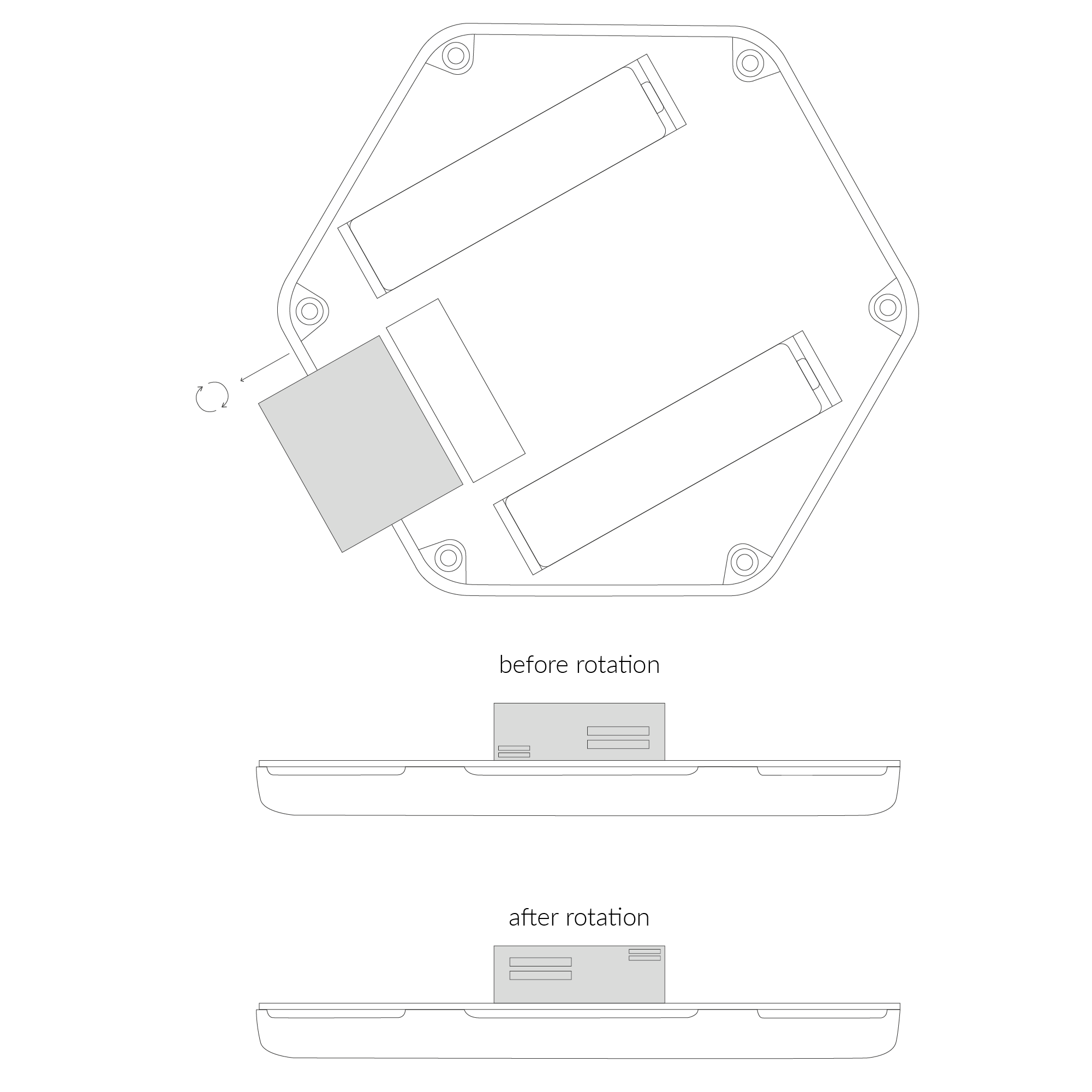
Figure 13. Rotating the PM sensor to prepare for a ceiling installation
Configuration
Configurable Parameters
A few parameters must be set before sending data to the gateway. The default firmware is configured in OTAA mode with predefined deveui, appkey (OTAA) and appskey, nwkskey (ABP).
Configuration of the device is stored in a JSON file divided into the following sections:
- info (generic, read only): information about the device,
- lorawan (generic): configuration data for LoRaWAN connection,
- ble (generic): Bluetooth settings,
- device (dynamic): individual configuration for a specific device (this section’s structure differs for each device),
- mainsens (dynamic): main sensors used for measurement of temperature, humidity, atmospheric pressure, total volatile organic compounds (TVOC), illuminance, carbon dioxide (CO2), sound pressure level (SPL) and differences in percentage value,
- pmxsense (dynamic): configuration of particulate matter sensor PM2.5, PM4 and PM10,
- intgassens (dynamic): configuration of replaceable sensor (see senstype parameter) measuring different types of gas, by default it's the CO sensor,
- extgassens (dynamic): configuration of additional custom sensor that can be plugged directly to the device I2C bus using a 5 pin socket on the PCB (disabled by default); for more information contact us on support@yosensi.io.
Sample configuration file for the YO Pure Pro device.
{
	"info": {
		"devmodel": "LNPP",
		"fwver": "3.6.1",
		"loraradio": "SX1261",
		"lorawanver": "1.0.2",
		"loraregion": "EU868",
		"blemacaddr": "0123456789ab"
	},
	"lorawan": {
		"subband": 1,
		"nwktype": "public",
		"acttype": "otaa",
		"otaa": {
			"deveui": "0123456789abcdef",
			"appeui": "fedcba9876543210",
			"appkey": "000102030405060708090a0b0c0d0e0f",
			"trials": 3
		},
		"abp": {
			"devaddr": "01234567",
			"nwkskey": "0123456789abcdef0123456789abcdef",
			"appskey": "000102030405060708090a0b0c0d0e0f"
	}
	},
	"ble": {
		"power": 0,
		"interval": 1600
	},
	"device": {
		"measinterval": 600
	},
	"pmxsens": {
		"enable": true,
		"pm4diffpct": 50,
		"pm10diffpct": 50,
		"pm25diffpct": 50
  	},
	"mainsens": {
		"co2diffpct": 50,
		"humdiffpct": 20,
		"spldiffpct": 50,
		"tempoffset": 0,
		"tempdiffpct": 20,
		"tvocdiffpct": 200,
		"lightdiffpct": 200,
		"pressdiffpct": 20
	},
	"extgassens": {
		"enable": false,
		"vrefval": 1060,
		"calibval": 1,
		"senstype": "CO",
		"sensdiffpct": 500
	},
	"intgassens": {
		"enable": true,
		"vrefval": 1060,
		"calibval": 230,
		"senstype": "CO",
		"sensdiffpct": 500
	}
}
OTAA & ABP
| OTAA | ABP |
|---|---|
| Device EUI | Device Address |
| Application EUI | Network Session Key |
| Application Key | Application Session Key |
| Number of Trials |
Generic Parameters
Click here to see the generic parameters for Yosensi devices.
Parameters
Device Parameters
| Name | Description | Possible Values | Default Value | Read/Write |
|---|---|---|---|---|
| measinterval | Measuring and sending interval LoRa [s] | 601-999999 | 600 | R/W |
| tempdiffpct | Measuring temperature threshold in % | 0-9999 | 20 | R/W |
| humdiffpct | Measuring humidity threshold in % | 0-9999 | 20 | R/W |
| pressdiffpct | Measuring pressure threshold in % | 0-9999 | 20 | R/W |
| lightdiffpct | Measuring luminosity threshold in % | 0-9999 | 200 | R/W |
| tvocdiffpct | Measuring Total Volatile Organic Compound threshold in % | 0-9999 | 200 | R/W |
| co2diffpct | Measuring CO2 threshold in % | 0-9999 | 50 | R/W |
| spldiffpct | Measuring sound pressure level threshold in % | 0-9999 | 50 | R/W |
| pm25diffpct | Measuring PM2.5 threshold in % | 0-9999 | 50 | R/W |
| pm4diffpct | Measuring PM4 threshold in % | 0-9999 | 50 | R/W |
| pm10diffpct | Measuring PM10 threshold in % | 0-9999 | 50 | R/W |
| tempoffset | Temperature offset in °C | -999.9-999.9 | 0 | R/W |
| enable | Enable or disable additional sensors such as PMx (default true), internal sensor (default true), and external (default false). | true, false | true | R/W |
| senstype | Type of sensor | CO, O3, EtOH, H2S, SO2, NO2 | CO | R/W |
| sensdiffpct | Measuring threshold of the additional sensor, value in [%] | 0-9999 | 1 | R/W |
| calibval | Calibration value of additional sensor, value should not be changed by user | 0-999999 | 1 | R/W |
| vrefval | Calibration electronic zero value of additional sensor, value should not be changed by user | 0-9999 | 1060 | R/W |
| ||||
Parameters description
- nwktype: used for setting the device in public or private network type.
- acttype: used for setting the device in ABP or OTAA mode.
- deveui, … , appskey: predefined addresses and keys, these parameters are generated using multiple IDs specific to the particular MCU and are unique for each device. They can be changed if needed.
- interval: determines the interval of sending broadcast packets, used to connect to every BLE receiver around the device.
- subband: used for setting the communication frequency sub-band in LoRaWAN.
- measinterval: measurement interval [s] between sending LoRa packets.
- tempdiffpct...pm10diffpct: the sensor measurement minimum percentage difference based on the previous two consecutive data points.
- tempoffset: the offset value subtracted from the temperature measurement.
- enable: an activation/deactivation indicator for a specic sensor i.e. PMx sensor, additional internal sensor. Default value ‘true’ is assigned to the PMx sensor and internal sensor. Additional external sensor has a default value false.
- senstype: corresponds to the alternate optional sensors connected to the internal socket, which is the CO sensor by default.
- sensdiffpct: for the sensor dened in senstype, the minimum percentage difference based on the previous two consecutive data points. Parameter is assigned to the section of internal sensor and external sensor.
WARNING: The calibval and vrefval parameters are pre-set to measure the values correctly. Changes to these values will affect measurements.
- calibval: the calibration value (i.e., sensitivity) of the additional gas sensor installed in the device, which is unique for each sensor and should not be adjusted until the sensor changes.
- vrefval: the calibration value (i.e., offset) of the additional gas sensor installed in the device, which is unique for each sensor circuit and should not be adjusted until the sensor changes.
Outlier detection mechanism
The xdiffpct configuration parameter set in the mainsens section define the sensitivity range for each data point used to determine if the subsequent measurement should be placed in the payload and sent to the server.
- If all values are within range, only the first and last values remain (see Figure 14).
- If measurements are out of range, the payload includes more than two points (see Figure 15).
In scenarios where too many data points exist such that they do not fit in one payload, they are sent in subsequent payloads with a reduced sending time despite the value configured in measinterval.
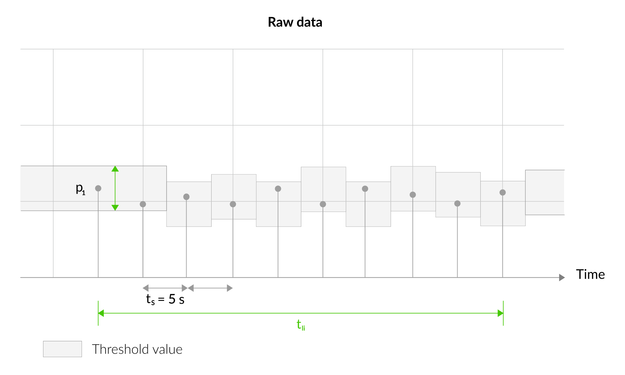
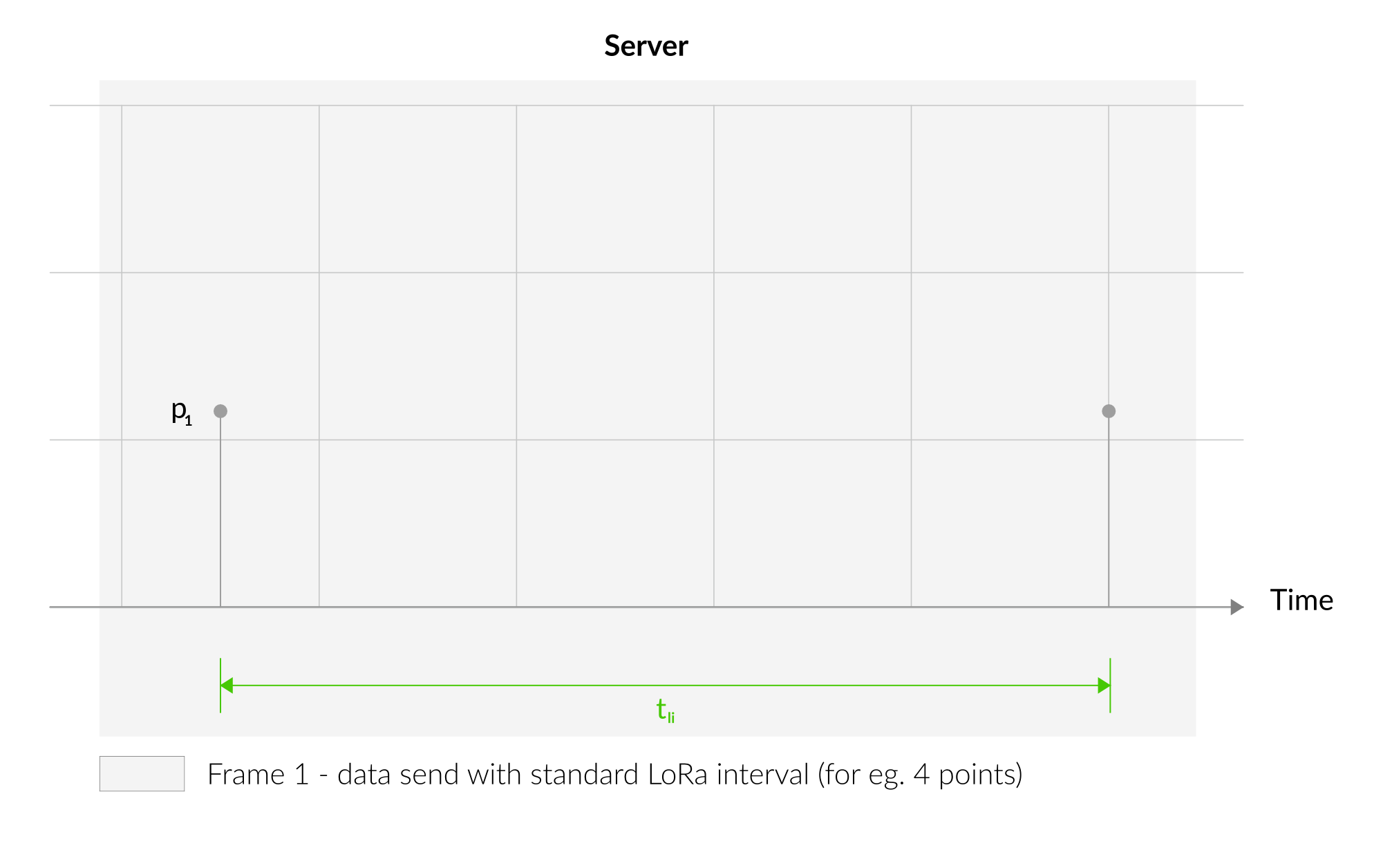
Figure 14. Outlier Detection Mechanism - 1
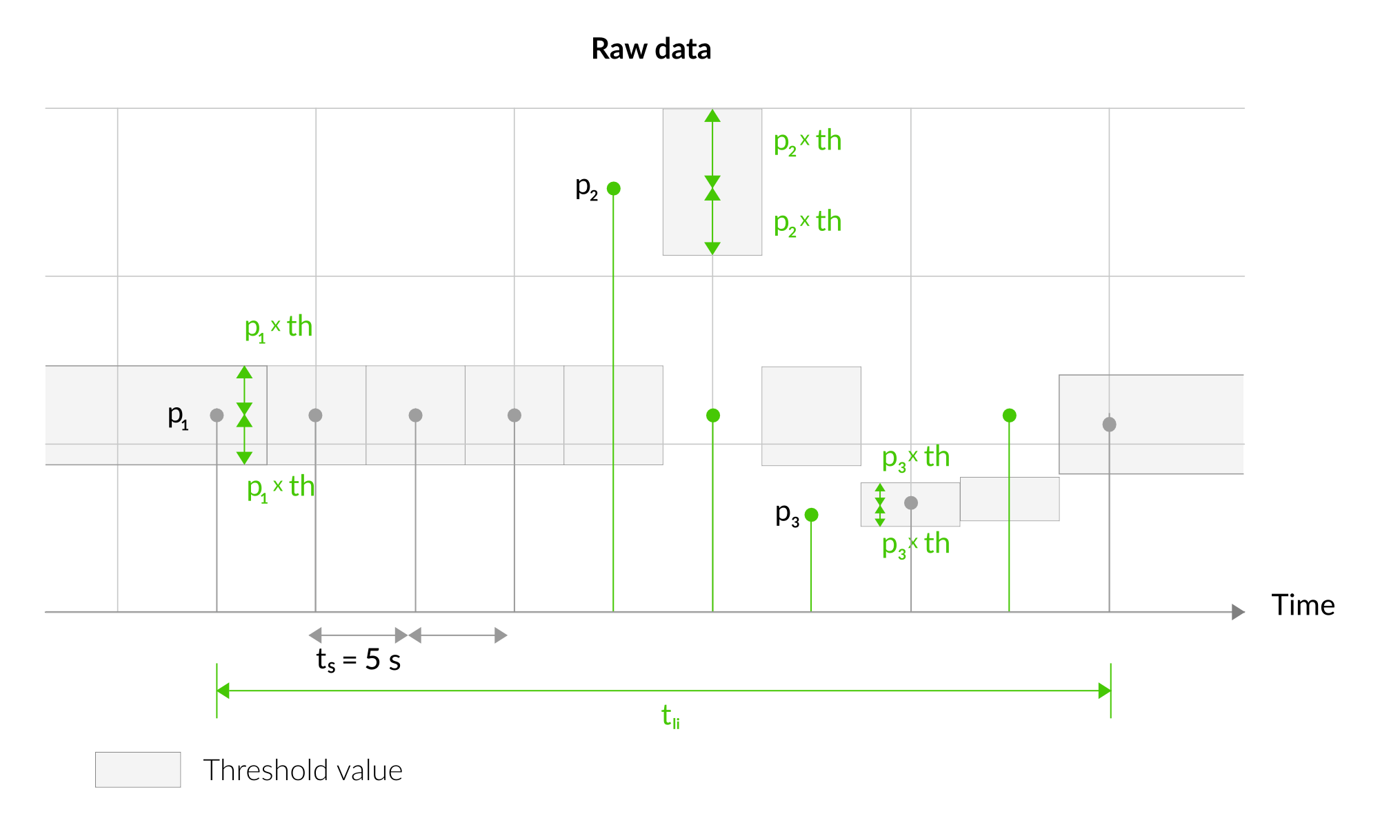
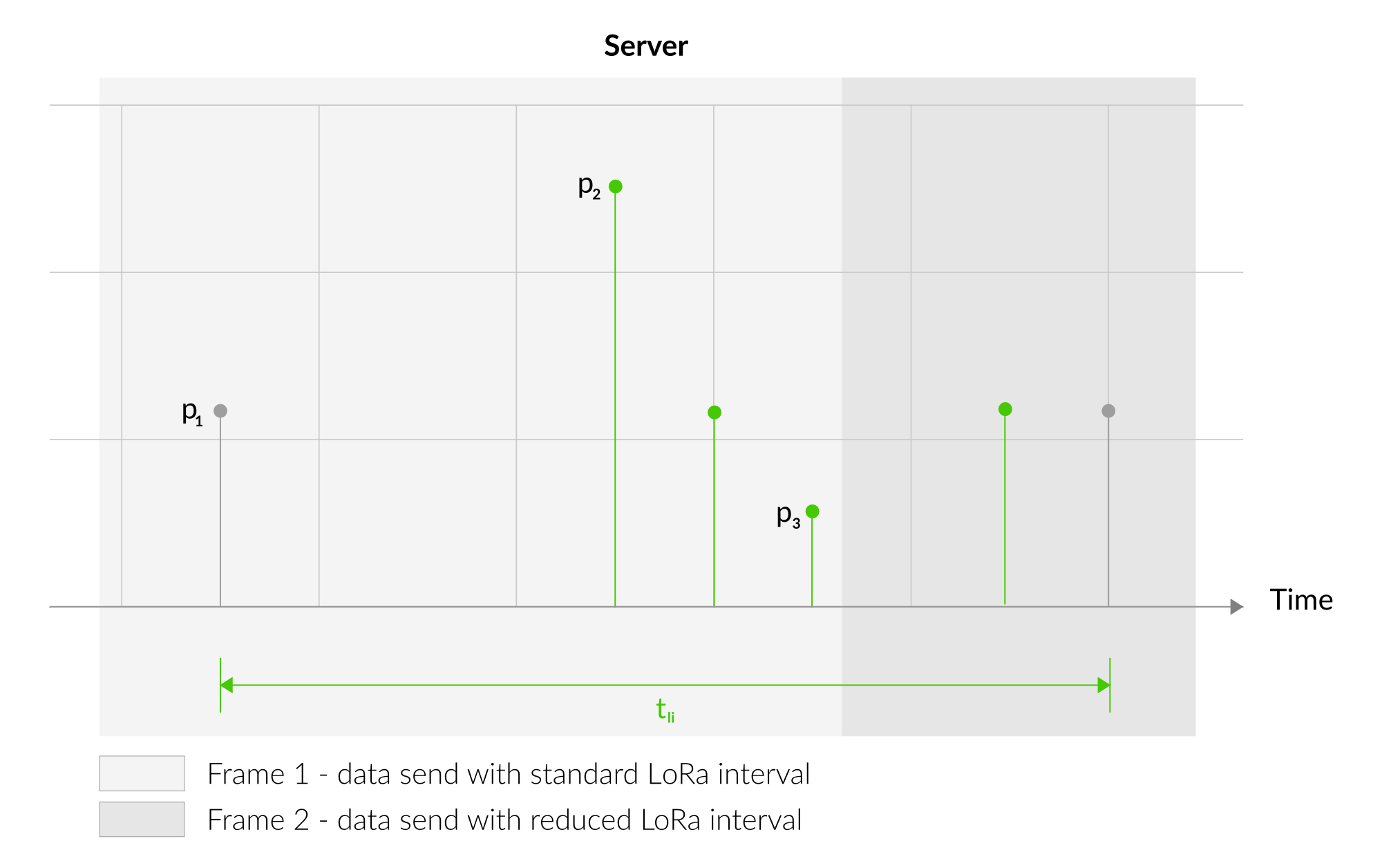
Figure 15. Outlier Detection Mechanism - 2
Downlink message
You can remotely adjust certain parameters by sending a downlink message through our platform. Simply navigate to the "COMMANDS" section for the selected device.
Update Measurement Interval
It is possible to change the measurement interval (measinterval) by using downlink. Information about changing the parameter will be sent from the server via the gateway.
Example of Downlink Message:
- Prefix:
0x03 - Measurement Index:
0x00 - Data (up to 4 bytes in hex):
0x0258
Sample Downlink: 0x03000258 - Sets a measurement interval of 600 seconds (10 minutes).
Update Min Temperature Measurement Difference
It is possible to change the minimum temperrature measurement difference percentage (tempdiffpct) by using downlink.
Example of Downlink Message:
- Prefix:
0x03 - Measurement Index:
0x01 - Data (up to 4 bytes in hex):
0x000A
Sample Downlink: 0x0301000A - Sets the minimum temperature measurement difference to 10%.
Update Min Humidity Measurement Difference
It is possible to change the minimum humidity measurement difference percentage (humdiffpct) by using downlink.
Example of Downlink Message:
- Prefix:
0x03 - Measurement Index:
0x02 - Data (up to 4 bytes in hex):
0x000F
Sample Downlink: 0x0302000F - Sets the minimum humidity measurement difference to 15%.
Update Min Pressure Measurement Difference
It is possible to change the minimum pressure measurement difference percentage (pressdiffpct) by using downlink.
Example of Downlink Message:
- Prefix:
0x03 - Measurement Index:
0x03 - Data (up to 4 bytes in hex):
0x0014
Sample Downlink: 0x03030014 - Sets the minimum pressure measurement difference to 20%.
Update Min Luminosity Measurement Difference
It is possible to change the minimum luminosity measurement difference percentage (lightdiffpct) by using downlink.
Example of Downlink Message:
- Prefix:
0x03 - Measurement Index:
0x04 - Data (up to 4 bytes in hex):
0x0019
Sample Downlink: 0x03040019 - Sets the minimum luminosity measurement difference to 25%.
Update Min TVOC Measurement Difference
It is possible to change the minimum TVOC measurement difference percentage (tvocdiffpct) by using downlink.
Example of Downlink Message:
- Prefix:
0x03 - Measurement Index:
0x05 - Data (up to 4 bytes in hex):
0x001e
Sample Downlink: 0x0305001e - Sets the minimum luminosity measurement difference to 30%.
Update Min CO2 Measurement Difference
It is possible to change the minimum CO2 measurement difference percentage (co2diffpct) by using downlink.
Example of Downlink Message:
- Prefix:
0x03 - Measurement Index:
0x06 - Data (up to 4 bytes in hex):
0x0023
Sample Downlink: 0x03060023 - Sets the minimum CO2 measurement difference to 35%.
Update Min Sound Pressure Level Measurement Difference
It is possible to change the minimum SPL measurement difference percentage (spldiffpct) by using downlink.
Example of Downlink Message:
- Prefix:
0x03 - Measurement Index:
0x07 - Data (up to 4 bytes in hex):
0x0028
Sample Downlink: 0x03070028 - Sets the minimum SPL measurement difference to 40%.
Update Temperature Offset Value
It is possible to change the Temperature offset value (tempoffset) by using downlink.
Example of Downlink Message:
- Prefix:
0x03 - Measurement Index:
0x08 - String Data (converted to hex):
2d36352e34
Sample Downlink: 0x03082d36352e34 - Sets the Temperature offset value to -65.4.
Click here to see how to connect a node using the Yosensi Management Platform.
See how to configure a node in Yosensi Management Platform
Check how to adopt and configure a node via the Yosensi App.
Take a look at the list of frequency plans used in Yosensi.
This datasheet describes the payload protocol developed by Yosensi for communicating with our devices.
Payload Decoder
If you want to connect to your own server, it is necessary to decode the specific payload for each device. To accomplish this, a payload decoder is required, which can be downloaded using the following link: Payload decoder. You can also use our integrated Payload Decoder here. Extended documentation of the protocol can be found in the Payload description on our website.
Compliance Statements
To view or download the Declaration of Conformity for YO Pure Pro go here