YO Meter Reader 2.0
Overview
Description
YO Meter Reader 2.0 is a LoRaWAN device designed for reading data from utility meters. It can be equipped with one of three types of external sensors: a LED Pulse Sensor, a Pulse Input Sensor or an IEC 62056-21 compatible interface. The LED Pulse Sensor enables remote reading of electricity or water consumption by detecting and counting LED pulses from compatible meters. The Pulse Input Sensor allows for the detection of electrical pulses from various types of utility meters, such as water, gas, or heat meters, by connecting to their pulse output. The IEC 62056-21 interface allows for optical data exchange with meters using this standard protocol, which is frequently found in electricity meters. In addition to these external sensing capabilities, the YO Meter Reader 2.0 features built-in temperature and humidity sensors.
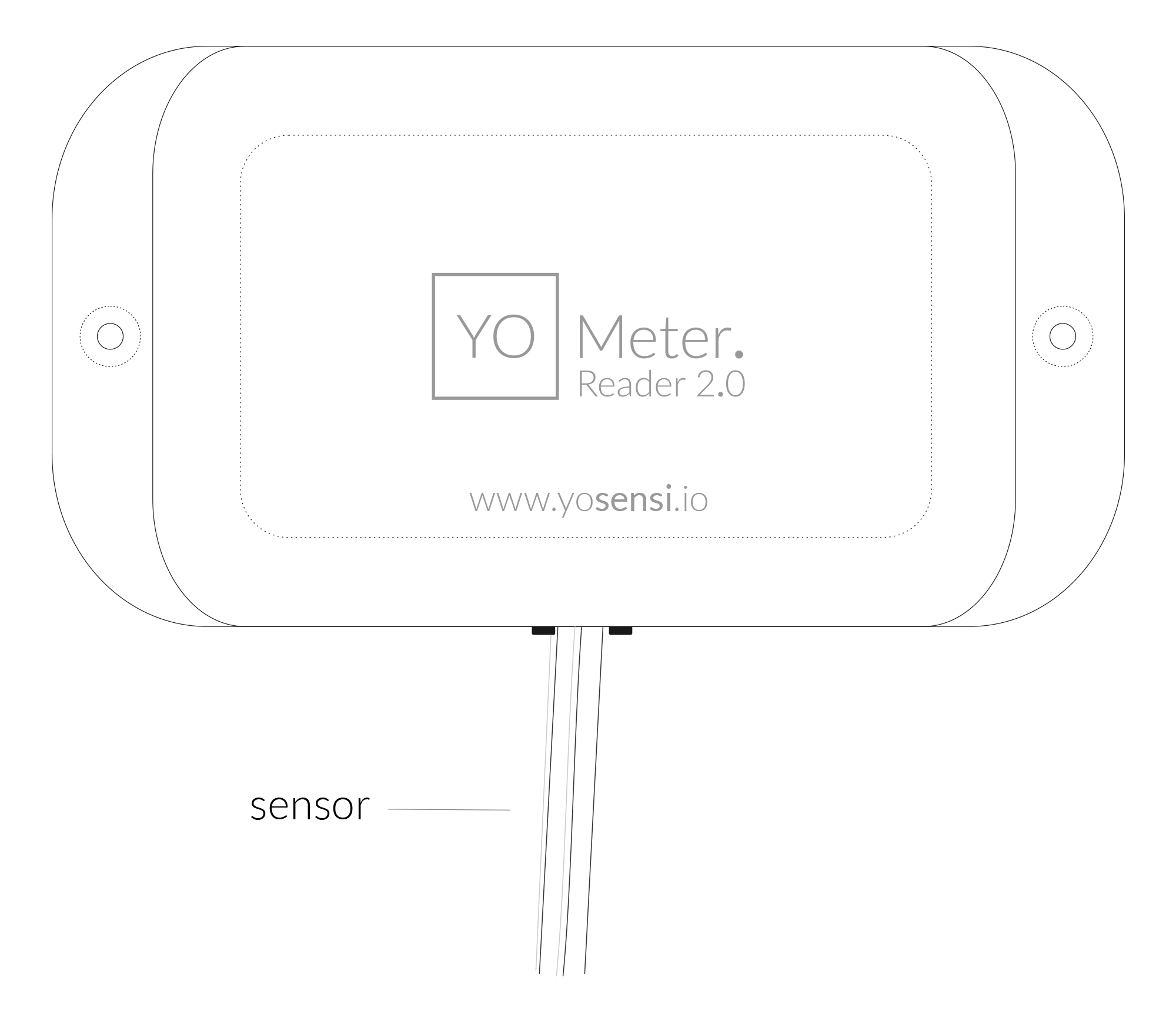

Figure 1. Device top view
Device sticker placed on the right side of the device enclosure contains information about model, version, LoRaWAN region and 3 parameters important in case of device identification and configuration:
- DEV EUI: 64-bit unique device identifier in a LoRaWAN network,
- DEV ADDR: address required to connect via ABP activation type to LoRaWAN,
- BLE MAC: Bluetooth physical address.
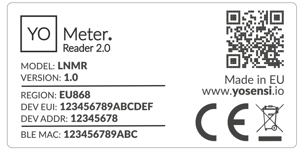
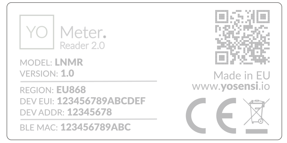
Figure 2. Device sticker
Features
- LoRaWAN Technology: Available in multiple versions with LoRa radio configured for various regions and ISM frequency bands (e.g., EU868, US915, AU915), it is compatible with both private and public LoRaWAN networks and supports connections via ABP (Activation by Personalization) or OTAA (Over-The-Air Activation).
- Bluetooth Low Energy (BLE): Enables easy configuration via a user-friendly JSON data exchange format. Supports firmware updates via OTA (Over-the-Air). Very low energy consumption
- Battery-Powered: Equipped with 3x AA lithium batteries featuring very low self-discharge, ensuring long-term operation without the need for an external power supply.
- Temperature and Relative Humidity: Measures temperature and relative humidity within the device enclosure, providing valuable insights into the surrounding environment.
- LED Pulse Sensor: Enables remote reading of electricity or water consumption by detecting and counting LED pulses from compatible meters.
- Pulse Input Sensor: Detects electrical pulses from various types of utility meters, such as water, gas, or heat meters, by connecting to their pulse output.
- IEC 62056-21 Interface: Allows for optical data exchange with meters using this standard protocol, which is frequently found in electricity meters.
- Yosensi Management Platform: Provides a web tool for device configuration, firmware updates, and infrastructure management. Enables comprehensive monitoring of transmitted data and easy device management.
- Yosensi Mobile App: Effortlessly manage devices with features to register new ones, configure settings, perform firmware updates, view/send logs, and test LoRaWAN connectivity. Learn more in our detailed Yosensi App blog post.
Specifications
Physical


Figure 3. Dimensions of the device
Device
| Attribute | Description |
|---|---|
| Dimensions | Height: 35 mm Width: 67,3 mm Depth: 124,3 mm |
| Colour | White |
| Mounting method | Horizontal Vertical (can be screwed to the wall) |
| Enclosure material | ABS |
| Level of protection | IP40 |
| Weight | 106 g (without batteries) |
LED Pulse Sensor


Figure 4. LED Sensor Dimensions
| Attribute | Description |
|---|---|
| Dimensions | Height: 11.6 mm Diameter: 27.2 mm |
| Colour | White |
| Enclosure material | Nylon |
| Level of protection | IP20 |
| Weight | 25 g |
Pulse Input Sensor
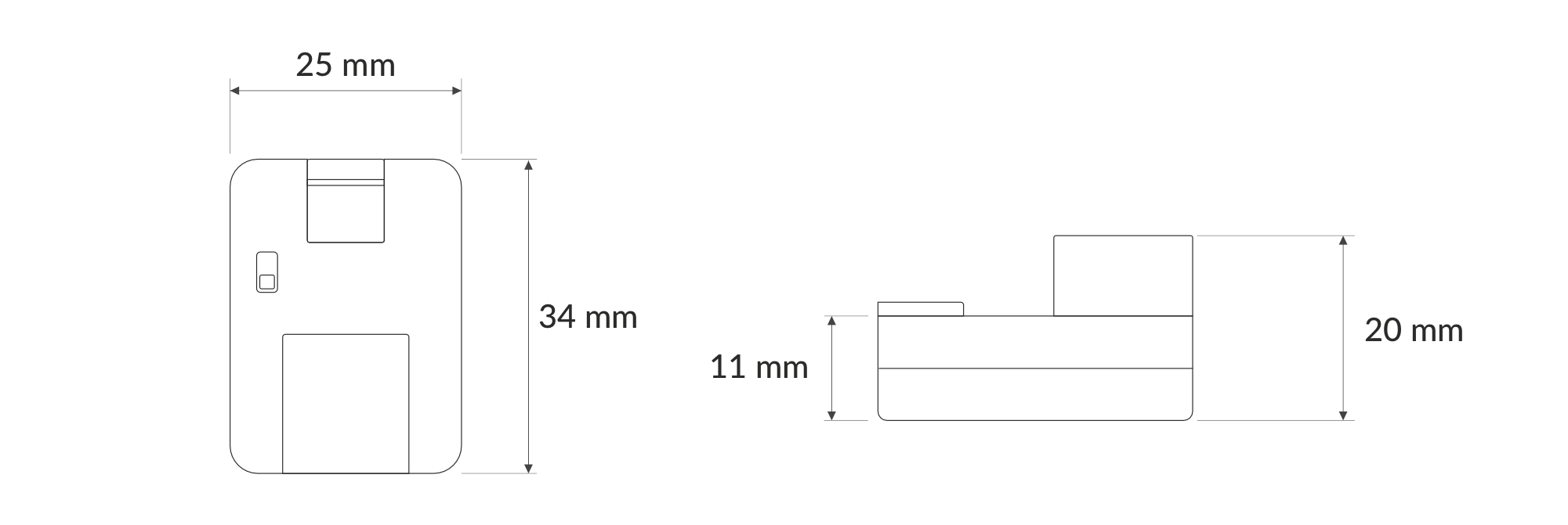

Figure 5. Pulse Input Sensor Dimensions
| Attribute | Description |
|---|---|
| Dimensions | Length: 34 mm Width: 25 mm Height: 20 mm |
| Colour | White |
| Enclosure material | Nylon |
| Level of protection | IP20 |
| Weight | 11 g |
IEC 62056-21 Interface Sensor
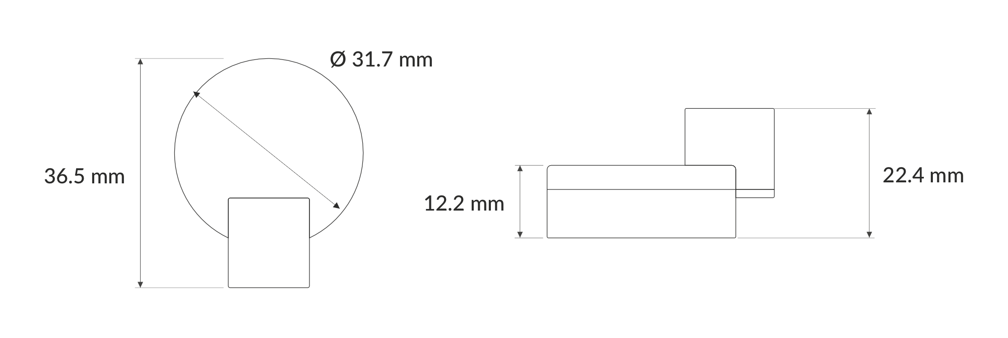

Figure 6. IEC 62056-21 Interface Sensor
| Attribute | Description |
|---|---|
| Dimensions | Length: 36.5 mm Height: 22.4 mm Diameter: 31.7 mm |
| Colour | White |
| Enclosure material | Nylon |
| Level of protection | IP20 |
| Weight | 40 g |
| Other | Magnet Included |
M-Bus (coming soon)
| Attribute | Description |
|---|---|
| Dimensions | TBD |
| Colour | TBD |
| Enclosure material | TBD |
| Level of protection | TBD |
| Weight | TBD |
Wireless M-Bus (coming soon)
| Attribute | Description |
|---|---|
| Dimensions | TBD |
| Colour | TBD |
| Enclosure material | TBD |
| Level of protection | TBD |
| Weight | TBD |
Operating Conditions
| Attribute | Description |
|---|---|
| Temperature | 0°C to 70°C |
| Humidity | 0 to 90% |
| Placement | Indoor use |
| Power supply | 3 x LR6 (AA) battery (3 x 1,5 V) |
| Power consumption | Maximum: 120 mA DC (4,5 V DC) |
Measured Values
| Parameter | Measurement range | Accuracy |
|---|---|---|
| Temperature | -40°C to 125°C | ±0.2°C (5°C to 60°C) |
| Relative humidity | 0% to 100% | ±2% (20% to 80%) |
| LED Pulse Sensor | ||
| Periodic counter | 0-2147483647 (int32) | - |
| Persistent counter | 0-2147483647 (int32) | - |
Utilities consumption | 0-214748364.7 (int32, precision 1) | - |
| Pulse Input Sensor | ||
| Periodic counter | 0-2147483647 (int32) | - |
| Persistent counter | 0-2147483647 (int32) | - |
| IEC 62056-21 Interface Sensor | Based on OBIS Readout | - |
| 1.8.0 / 2.8.0 Total active energy consumed / returned to the grid | kWh (floating point) | Based on meter |
| 1.8.1 / 2.8.1 Active energy in tariff I consumed / returned to the grid | kWh (floating point) | Based on meter |
| 1.8.2 / 2.8.2 Active energy in tariff II consumed / returned to the grid | kWh (floating point) | Based on meter |
| 1.8.3 / 2.8.3 Active energy in tariff III consumed / returned to the grid | kWh (floating point) | Based on meter |
| 1.8.4 / 2.8.4 Active energy in tariff IV consumed / returned to the grid | kWh (floating point) | Based on meter |
| 15.8.0 / F.8.0 Total absolute active energy | kWh (floating point) | Based on meter |
| 15.8.1 / F.8.1 Absolute active energy in tariff I | kWh (floating point) | Based on meter |
| 15.8.2 / F.8.2 Absolute active energy in tariff II | kWh (floating point) | Based on meter |
| 15.8.3 / F.8.3 Absolute active energy in tariff III | kWh (floating point) | Based on meter |
| 15.8.4 / F.8.4 Absolute active energy in tariff IV | kWh (floating point) | Based on meter |
| 21.8.0 / 22.8.0 Total active energy in phase I consumed / returned to the grid | kWh (floating point) | Based on meter |
| 41.8.0 / 42.8.0 Total active energy in phase II consumed / returned to the grid | kWh (floating point) | Based on meter |
| 61.8.0 / 62.8.0 Total active energy in phase III consumed / returned to the grid | kWh (floating point) | Based on meter |
| 35.8.0 Total absolute active energy in phase I | kWh (floating point) | Based on meter |
| 55.8.0 Total absolute active energy in phase II | kWh (floating point) | Based on meter |
| 75.8.0 Total absolute active energy in phase III | kWh (floating point) | Based on meter |
| 3.8.0 / 4.8.0 Total reactive energy received from / returned to the grid | kvarh (floating point) | Based on meter |
| 3.8.1 / 4.8.1 Reactive energy in tariff I received from / returned to the grid | kvarh (floating point) | Based on meter |
| 3.8.2 / 4.8.2 Reactive energy in tariff II received from / returned to the grid | kvarh (floating point) | Based on meter |
| 3.8.3 / 4.8.3 Reactive energy in tariff III received from / returned to the grid | kvarh (floating point) | Based on meter |
| 3.8.4 / 4.8.4 Reactive energy in tariff IV received from / returned to the grid | kvarh (floating point) | Based on meter |
| 5.8.0 / 6.8.0 / 7.8.0 / 8.8.0 Total reactive energy in quadrant I / quadrant II / quadrant III / quadrant IV | kvarh (floating point) | Based on meter |
| 5.8.1 / 5.8.2 / 5.8.3 / 5.8.4 Reactive energy in quadrant I in tariff I / tariff II / tariff III / tariff IV | kvarh (floating point) | Based on meter |
| 6.8.1 / 6.8.2 / 6.8.3 / 6.8.4 Reactive energy in quadrant II in tariff I / tariff II / tariff III / tariff IV | kvarh (floating point) | Based on meter |
| 7.8.1 / 7.8.2 / 7.8.3 / 7.8.4 Reactive energy in quadrant III in tariff I / tariff II / tariff III / tariff IV | kvarh (floating point) | Based on meter |
| 8.8.1 / 8.8.2 / 8.8.3 / 8.8.4 Reactive energy in quadrant IV in tariff I / tariff II / tariff III / tariff IV | kvarh (floating point) | Based on meter |
| 9.8.0 Total apparent energy | kVAh (floating point) | Based on meter |
| 9.8.1 Apparent energy in tariff I | kVAh (floating point) | Based on meter |
| 9.8.2 Apparent energy in tariff II | kVAh (floating point) | Based on meter |
| 9.8.3 Apparent energy in tariff III | kVAh (floating point) | Based on meter |
| 9.8.4 Apparent energy in tariff IV | kVAh (floating point) | Based on meter |
| 1.6.0 / 2.6.0 Total positive / negative maximum active demand | kW (floating point) | Based on meter |
| 1.6.1 / 2.6.1 Positive / negative maximum active demand in tariff I | kW (floating point) | Based on meter |
| 1.6.2 / 2.6.2 Positive / negative maximum active demand in tariff II | kW (floating point) | Based on meter |
| 1.6.3 / 2.6.3 Positive / negative maximum active demand in tariff III | kW (floating point) | Based on meter |
| 1.6.4 / 2.6.4 Positive / negative maximum active demand in tariff IV | kW (floating point) | Based on meter |
| 15.6.0 Total absolute active power maximum demand | kW (floating point) | Based on meter |
| 15.6.1 Absolute active maximum demand in tariff I | kW (floating point) | Based on meter |
| 15.6.2 Absolute active maximum demand in tariff II | kW (floating point) | Based on meter |
| 15.6.3 Absolute active maximum demand in tariff III | kW (floating point) | Based on meter |
| 15.6.4 Absolute active maximum demand in tariff IV | kW (floating point) | Based on meter |
| 3.6.0 / 4.6.0 Total positive / negative maximum reactive demand | kvar (floating point) | Based on meter |
| 9.6.0 Total maximum apparent demand | kVA (floating point) | Based on meter |
| 1.7.0 / 2.7.0 Positive / negative instantaneous active power | kW (floating point) | Based on meter |
| 21.7.0 / 22.7.0 Positive / negative instantaneous active power in phase I | kW (floating point) | Based on meter |
| 41.7.0 / 42.7.0 Positive / negative instantaneous active power in phase II | kW (floating point) | Based on meter |
| 61.7.0 / 62.7.0 Positive / negative instantaneous active power in phase III | kW (floating point) | Based on meter |
| 15.7.0 Absolute active instantaneous power | kW (floating point) | Based on meter |
| 35.7.0 / 55.7.0 / 75.7.0 Absolute active instantaneous power in phase I / phase II / phase III | kW (floating point) | Based on meter |
| 3.7.0 / 4.7.0 Positive / negative instantaneous reactive power | kvar (floating point) | Based on meter |
| 23.7.0 / 24.7.0 Positive / negative instantaneous reactive power in phase I | kvar (floating point) | Based on meter |
| 43.7.0 / 44.7.0 Positive / negative instantaneous reactive power in phase II | kvar (floating point) | Based on meter |
| 63.7.0 / 64.7.0 Positive / negative instantaneous reactive power in phase III | kvar (floating point) | Based on meter |
| 9.7.0 Instantaneous apparent power | kVA (floating point) | Based on meter |
| 29.7.0 / 49.7.0 / 69.7.0 Instantaneous apparent power in phase I / phase II / phase III | kVA (floating point) | Based on meter |
| 11.6.0 Maximal current | A (floating point) | Based on meter |
| 31.6.0 Maximal current in phase I | A (floating point) | Based on meter |
| 51.6.0 Maximal current in phase II | A (floating point) | Based on meter |
| 71.6.0 Maximal current in phase III | A (floating point) | Based on meter |
| 91.6.0 Maximal current in phase IV | A (floating point) | Based on meter |
| 11.7.0 Instantaneous current | A (floating point) | Based on meter |
| 31.7.0 / 51.7.0 / 71.7.0 / 91.7.0 Instantaneous current in phase I / phase II / phase III / neutral | V (floating point) | Based on meter |
| 12.7.0 Maximal / instantaneous voltage | V (floating point) | Based on meter |
| 32.7.0 / 52.7.0 / 72.7.0 Instantaneous voltage in phase I / phase II / phase III | V (floating point) | Based on meter |
| 13.7.0 Instantaneous power factor | - (floating point) | Based on meter |
| 33.7.0 / 53.7.0 / 73.7.0 Instantaneous power factor in phase L1 / phase L2 / phase L3 | - (floating point) | Based on meter |
| 14.7.0 Frequency in the installation | Hz (floating point) | Based on meter |
OBIS Code
An OBIS code is a numerical identifier representing the specific physical quantity measured by a meter. Here’s an example (your energy meter might show it in a simplified form):
1.7.0(245.12*kW)
This consists of three parts: the OBIS code (1.7.0), the reading (245.12), and the unit (kW), separated by specific symbols. In this case, the OBIS code 1.7.0 represents the instantaneous active power currently being drawn from the grid.
Why 1.7.0? This is defined in the IEC62056-21 standard, which establishes how OBIS codes must be represented on most energy and utility meters within the EU.
OBIS registers
According to the standard, it's possible to expose not only classic measurement values such as power, energy, and voltage, but also additional data like the meter’s operating status. However, let’s focus particularly on the classic measurement values.
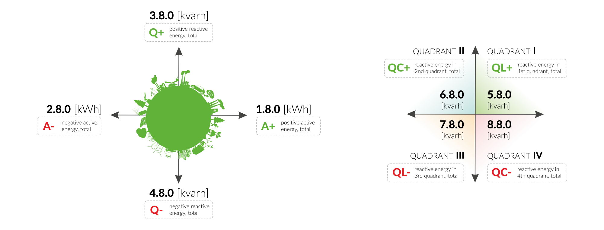
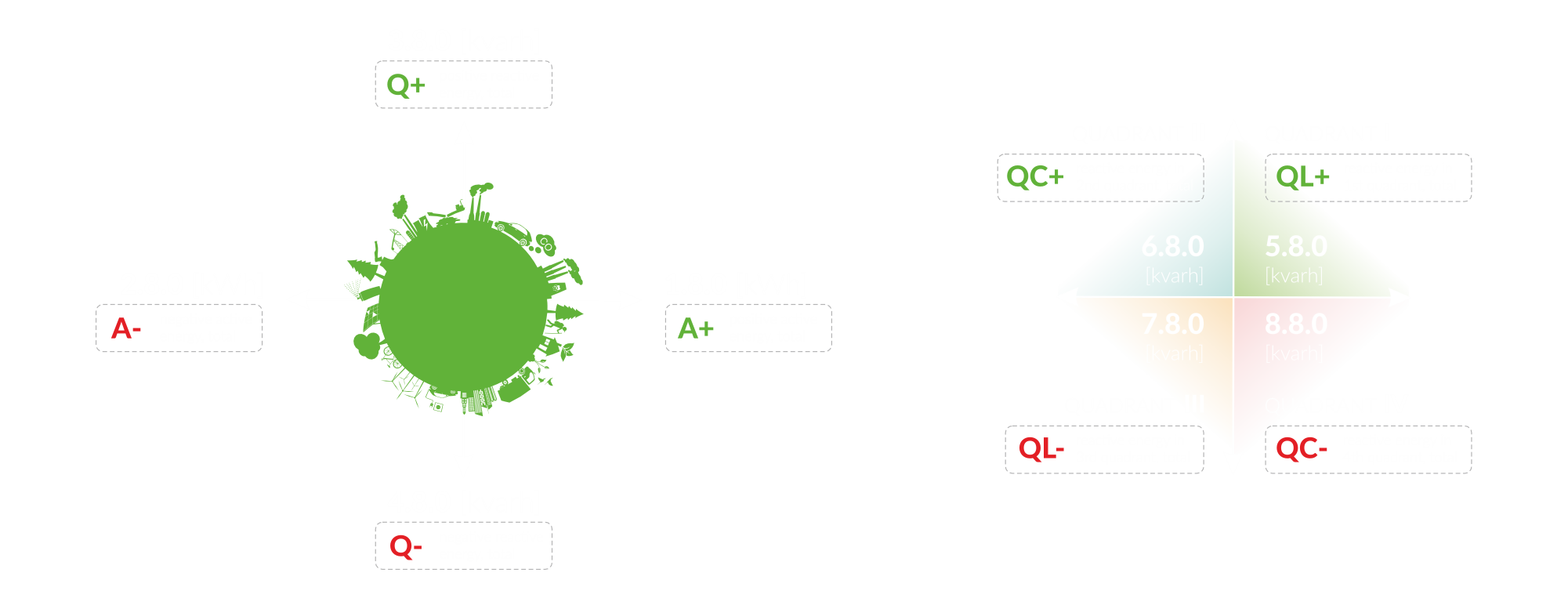
Figure 7. OBIS
In summary, active energy refers to the energy used by an electrical device that’s directly converted into work or heat. Reactive energy, on the other hand, describes the energy stored within the device, necessary for its function but not converted into work, and can lead to energy losses for the grid operator. Energy is considered positive when it’s drawn from the grid, and negative when it’s supplied back, such as through solar panel production. The type of reactive energy depends on its nature: it can be more capacitive, more inductive, resistive, or a mix of these types.
Controls and Indicators
LED Status Indicator
YO Meter Reader 2.0 communicates its current behaviour to the user by RGBW LED placed on the side.
Diode statuses interpretation
| Behavior | Colour | Status |
|---|---|---|
| Single flash | Green | General: device is working correctly (power and memory). |
| Single flash | Red | General: device is working incorrectly (power and memory). LoRaWAN communication: failed to receive an acknowledgement from LoRaWAN Server within specified timeout. |
| Single flash | White | LoRaWAN communication: LoRaWAN frame sent / confirmation from LoRaWAN Server after receiving the frame. |
| Slow flashing | Blue | BLE communication: connection to the device via BLE (configuration). |
| Rapid flashing | Blue | LoRaWAN communication: connecting to LoRaWAN network. |
External Sensors LEDs
LED Pulse sensor
| Behavior | Colour | Status |
|---|---|---|
| Single flash | Red | Sensor detects a pulse. |
| Solid light | Red | Sensor is overexposed or receiving too much ambient light. |
Pulse Input sensor
| Behavior | Colour | Status |
|---|---|---|
| Single flash | Red | Sensor detects a pulse. |
IEC 62056-21 interface
| Behavior | Colour | Status |
|---|---|---|
| Single flash | Red | Sensor request data. |
| Rapid Flashing | Red | Sensor data read process. |
Buttons
The YO Meter Reader 2.0 has a button for resetting the device. Figure 8 shows its placement. To reboot the device, press the reset button for a moment, e.g. with a thin stick.


Figure 8. Reset button
The Pulse Input Sensor has a switch for choosing between Potential Contact and Potential Free Contact. Figure 9 shows its placement and function.
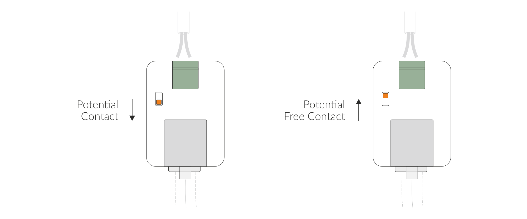
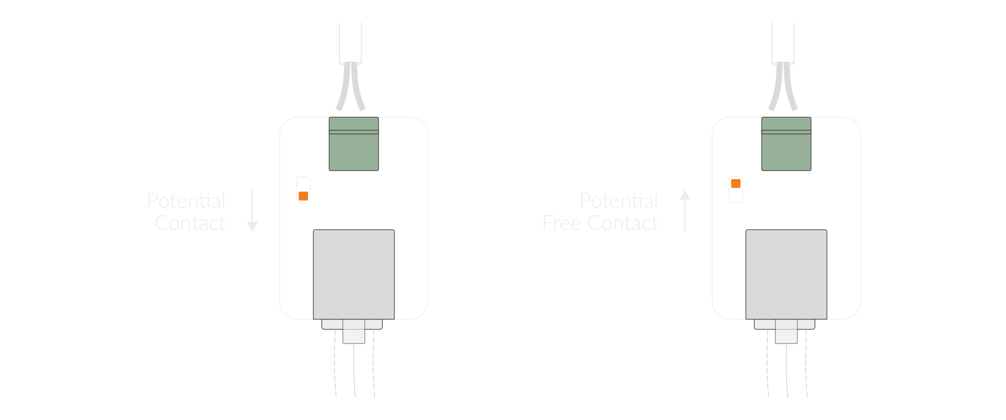
Figure 9. Pulse Input Sensor switch
Installation
Package Contents
- Device (without batteries).
- External meter (selected when ordered).
- Warranty card.
Safety Precautions
Go to the Safety Precautions section to see important information on handling, disposal and maintenance.
Installation Guide
- Connect the sensor to the RJ12 socket in the device.
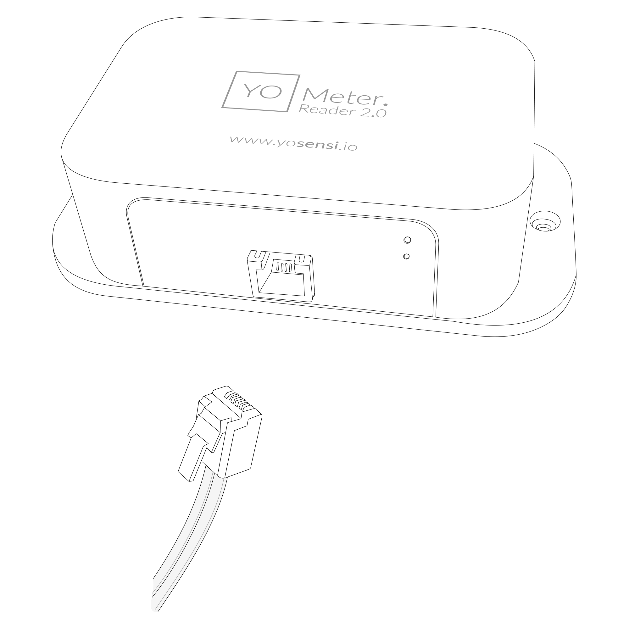
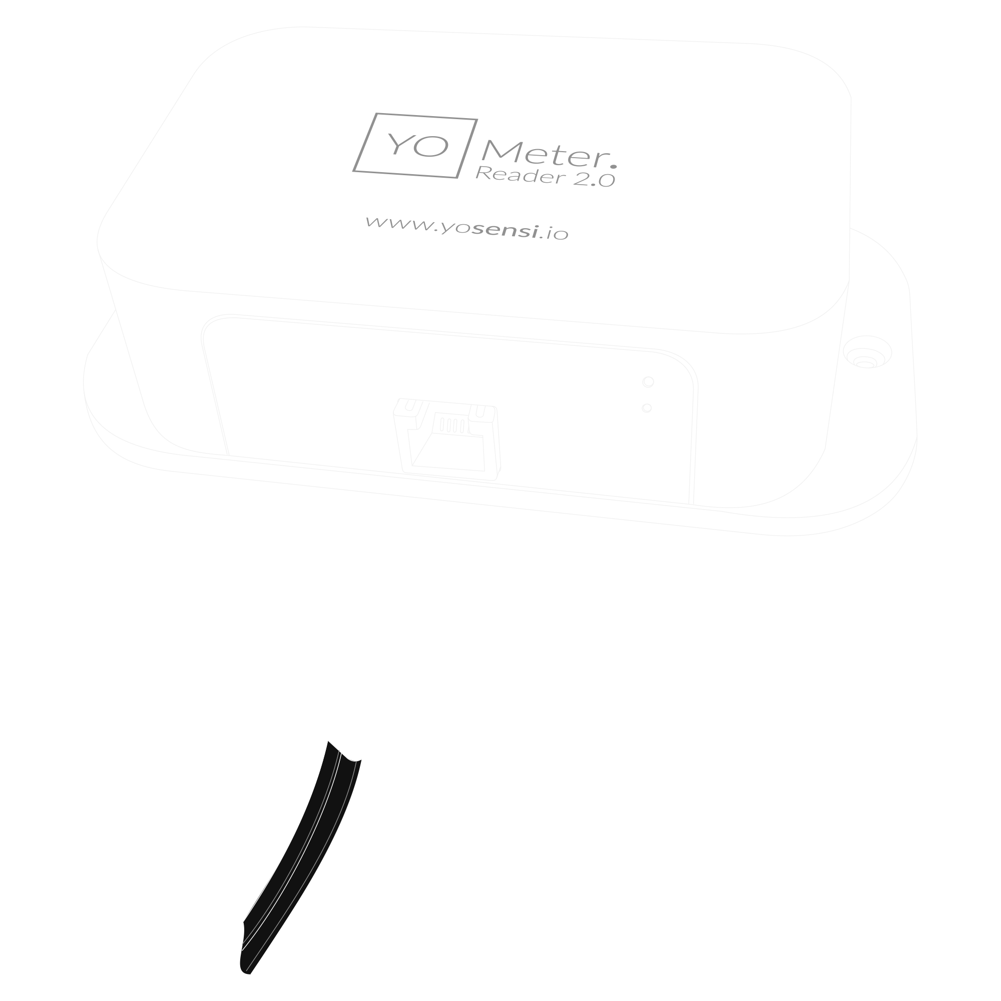
Figure 10. Connecting sensor to the device
- Unscrew the device: remove 4 screws from the enclosure.
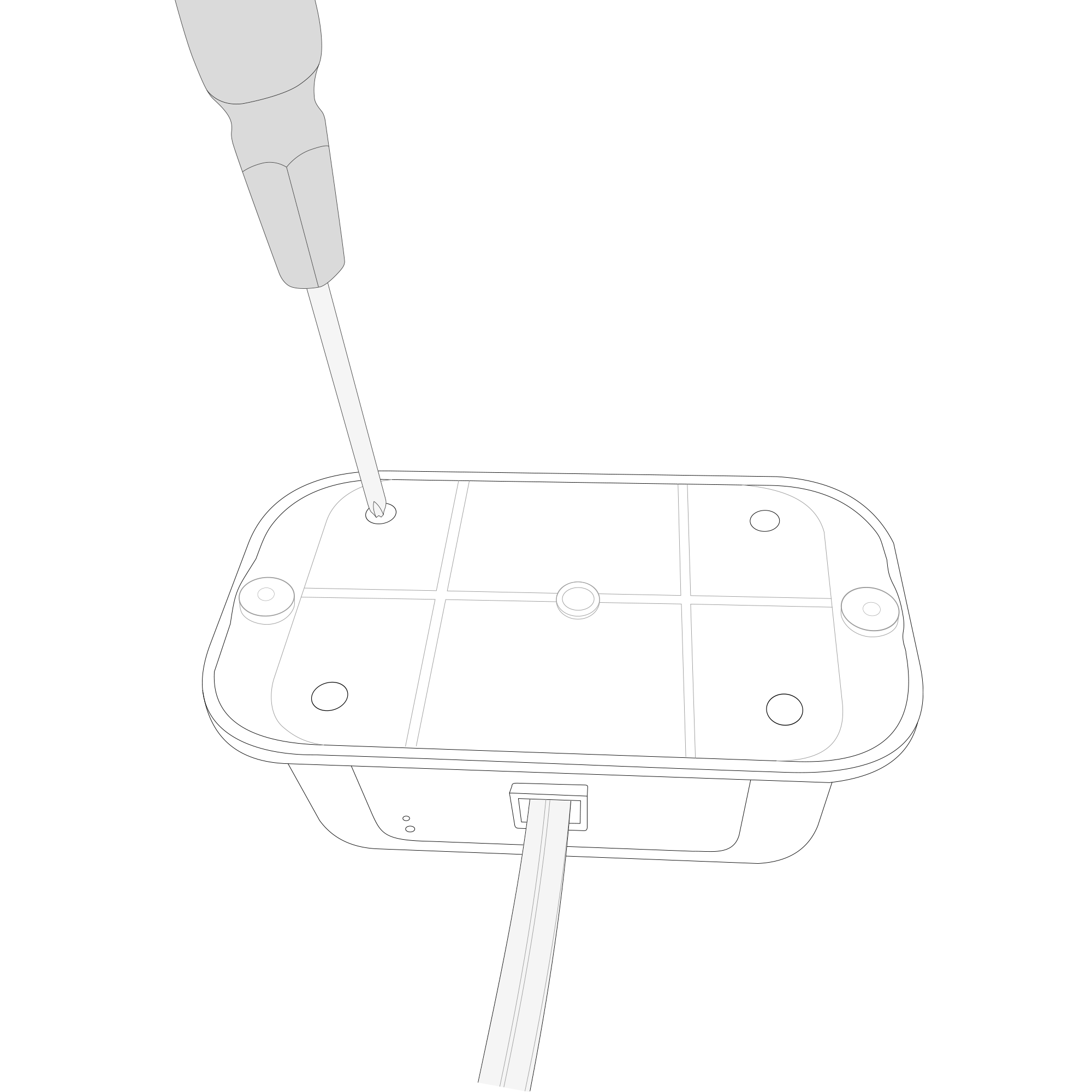
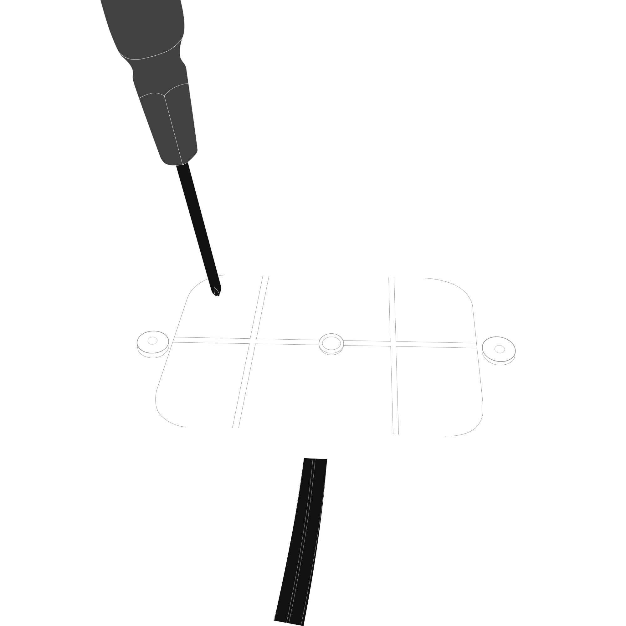
Figure 11. Back view of the device
- Place three LR6 (AA) batteries in the device according to the polarity indicated on the battery holder.
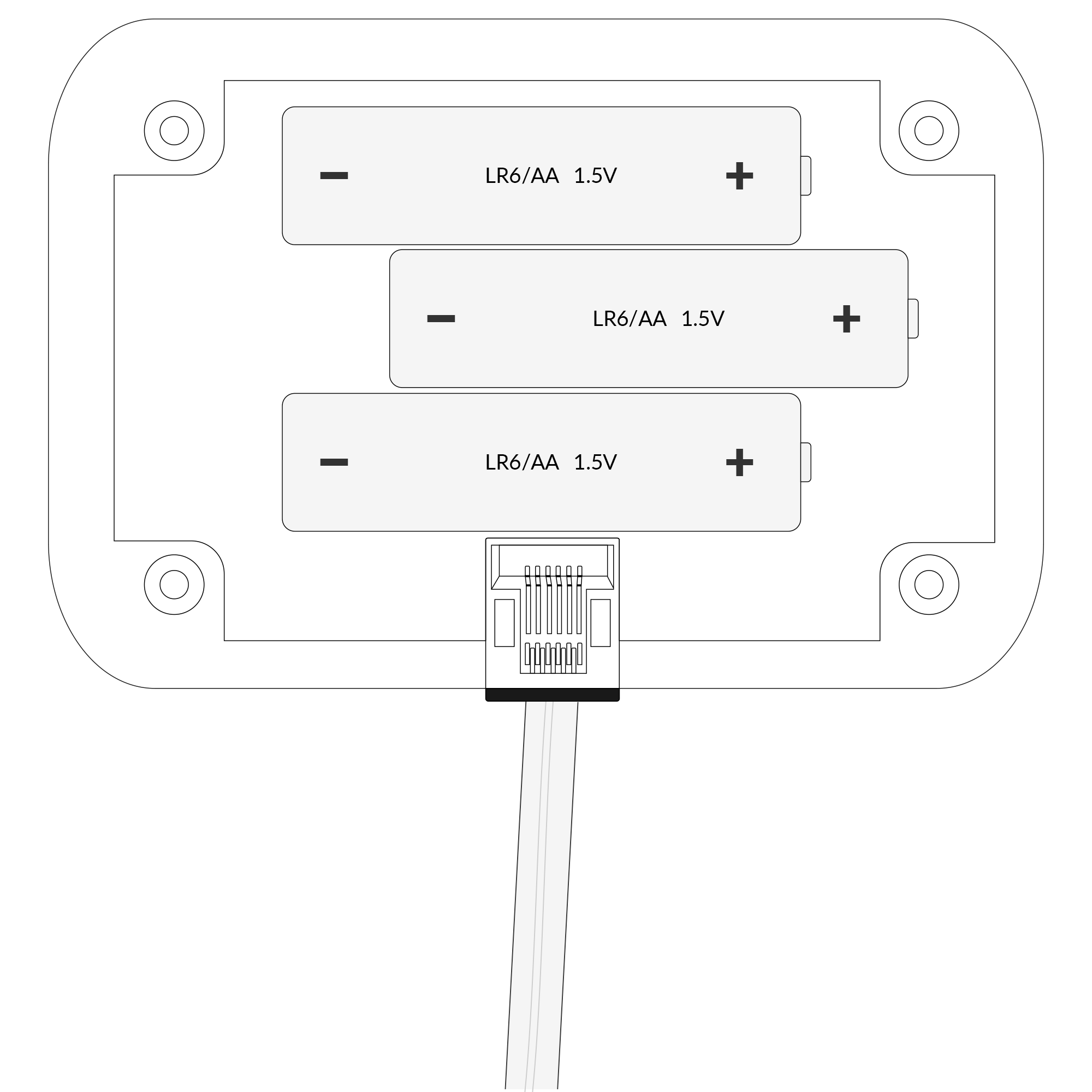
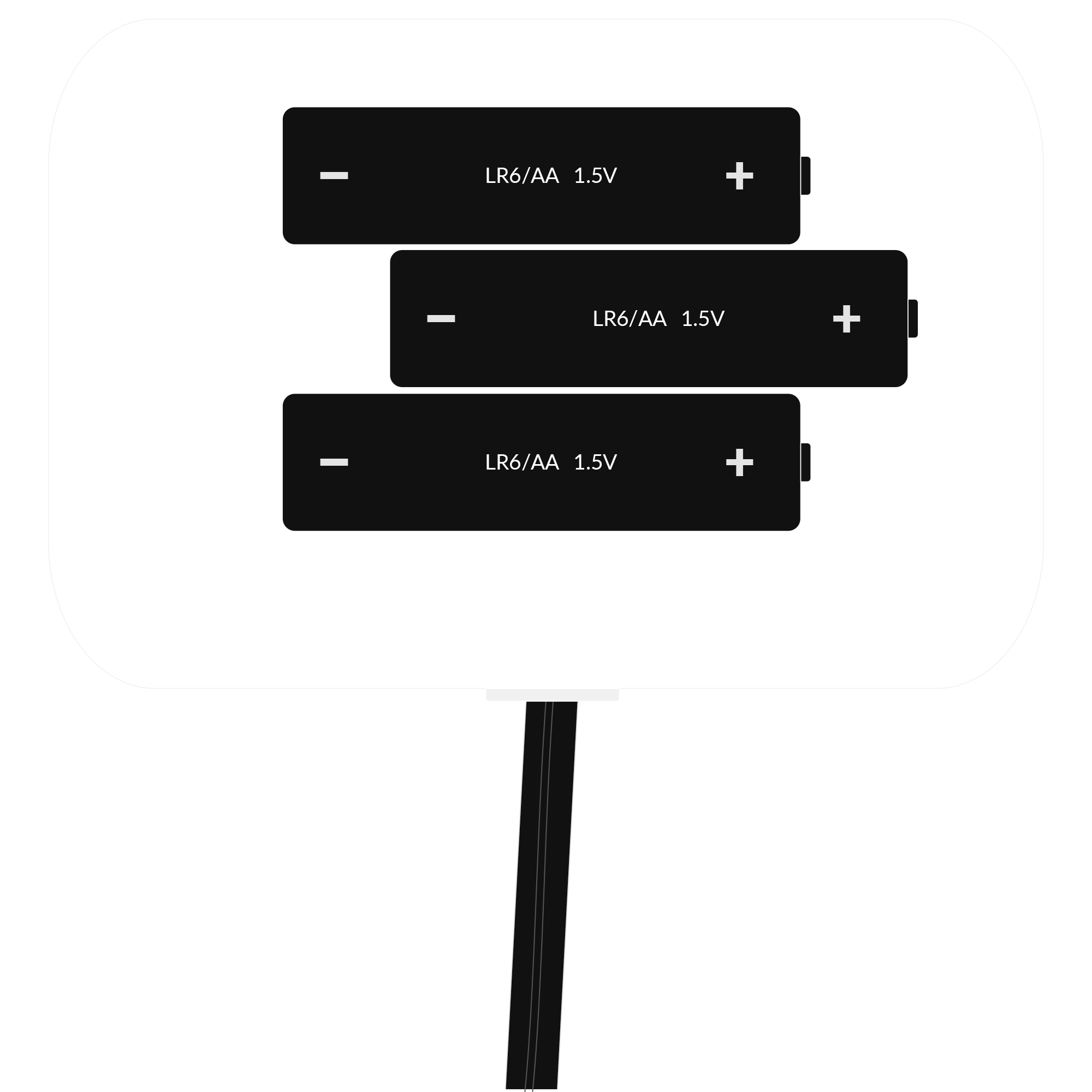
Figure 12. Battery placement instructions
-
Assemble the device and screw it back together.
-
Installation of the sensor: IEC 62056-21 interface or LED Pulse Each sensor enclosure features a sliding part at the bottom that facilitates installation. To install the sensor, first, remove the sliding part from the sensor enclosure and attach it to the appropriate spot on the meter. Once securely fixed, slide the sensor onto the mounted part, ensuring it is properly positioned. As for the Pulse Input sensor, it simply attaches to the measuring device.
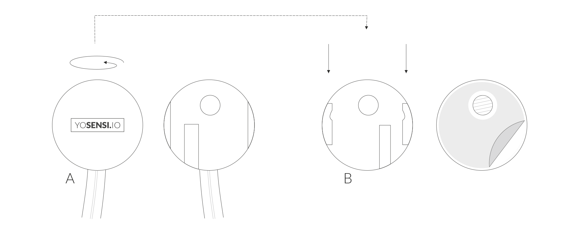
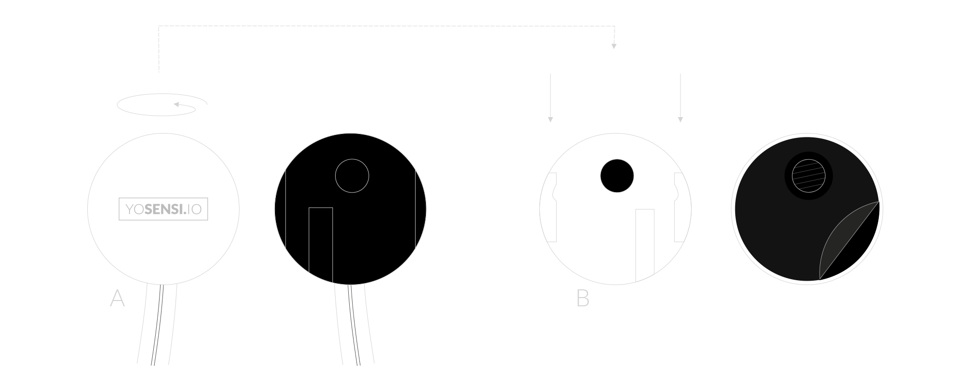
Figure 13. LED Pulse sensor
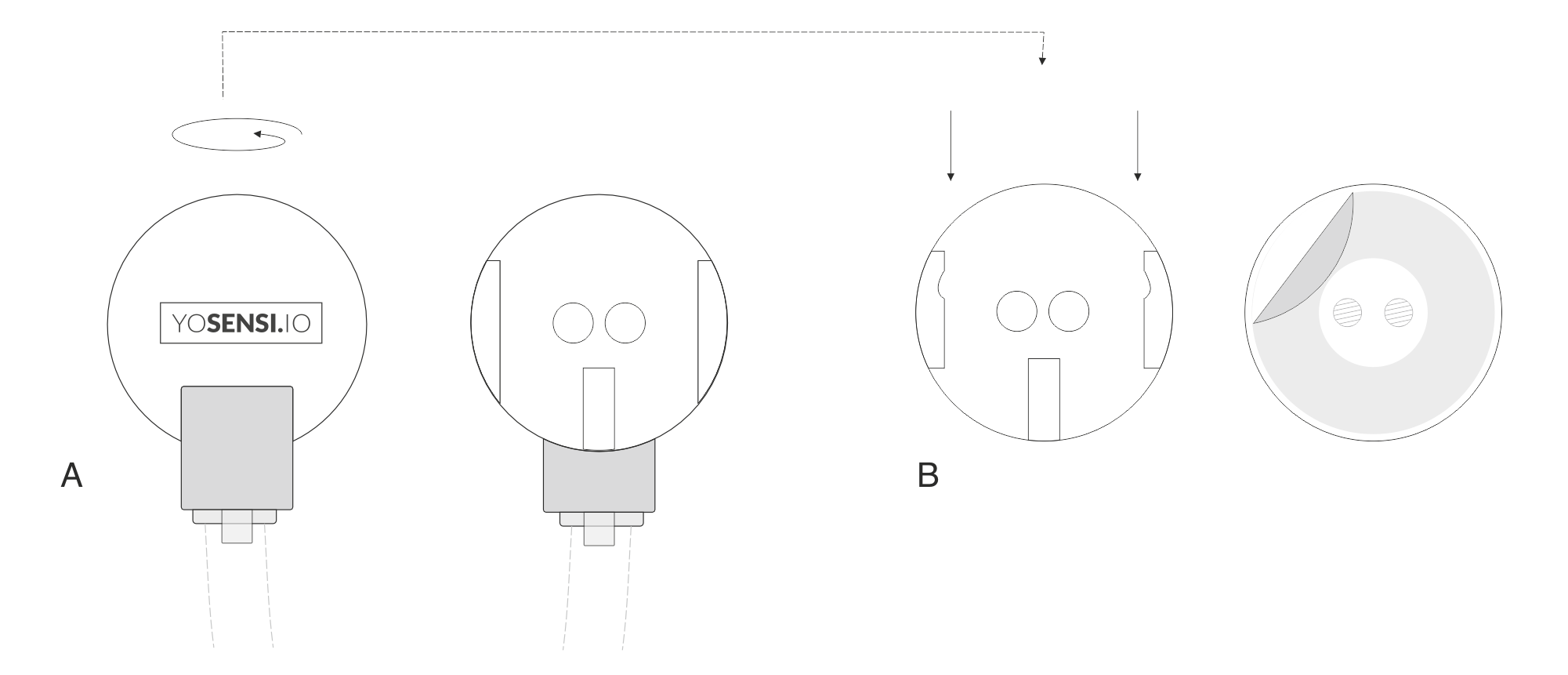
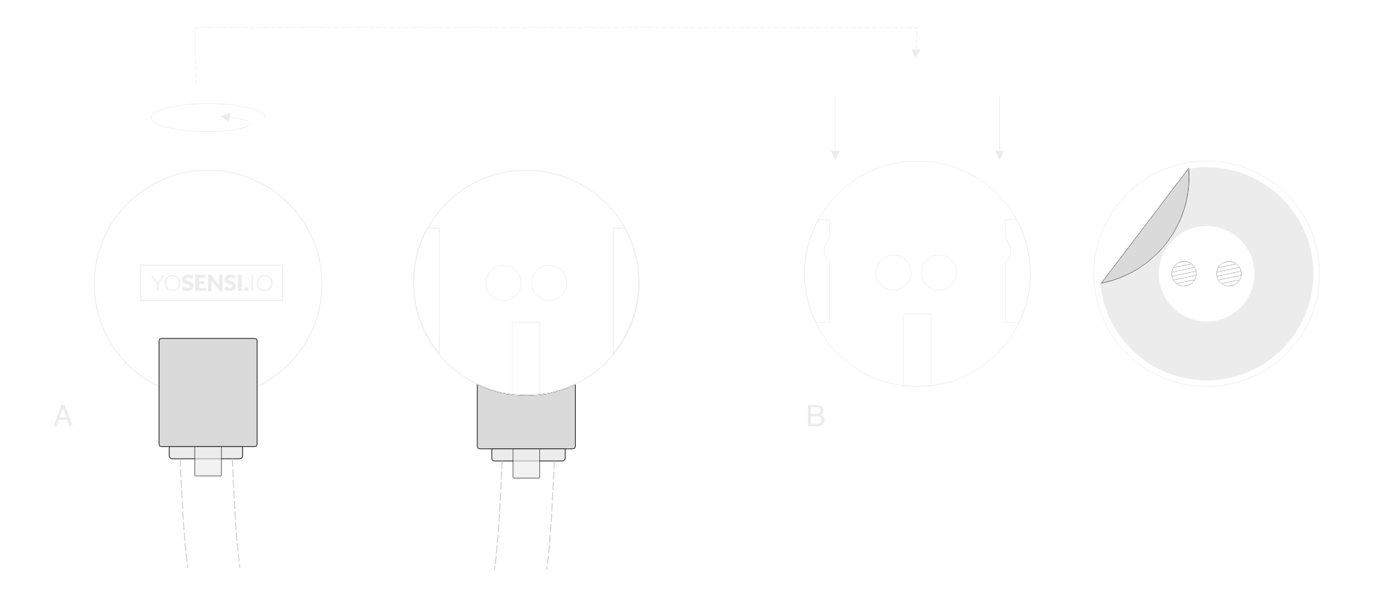
Figure 14. IEC 62056-21 interface sensor
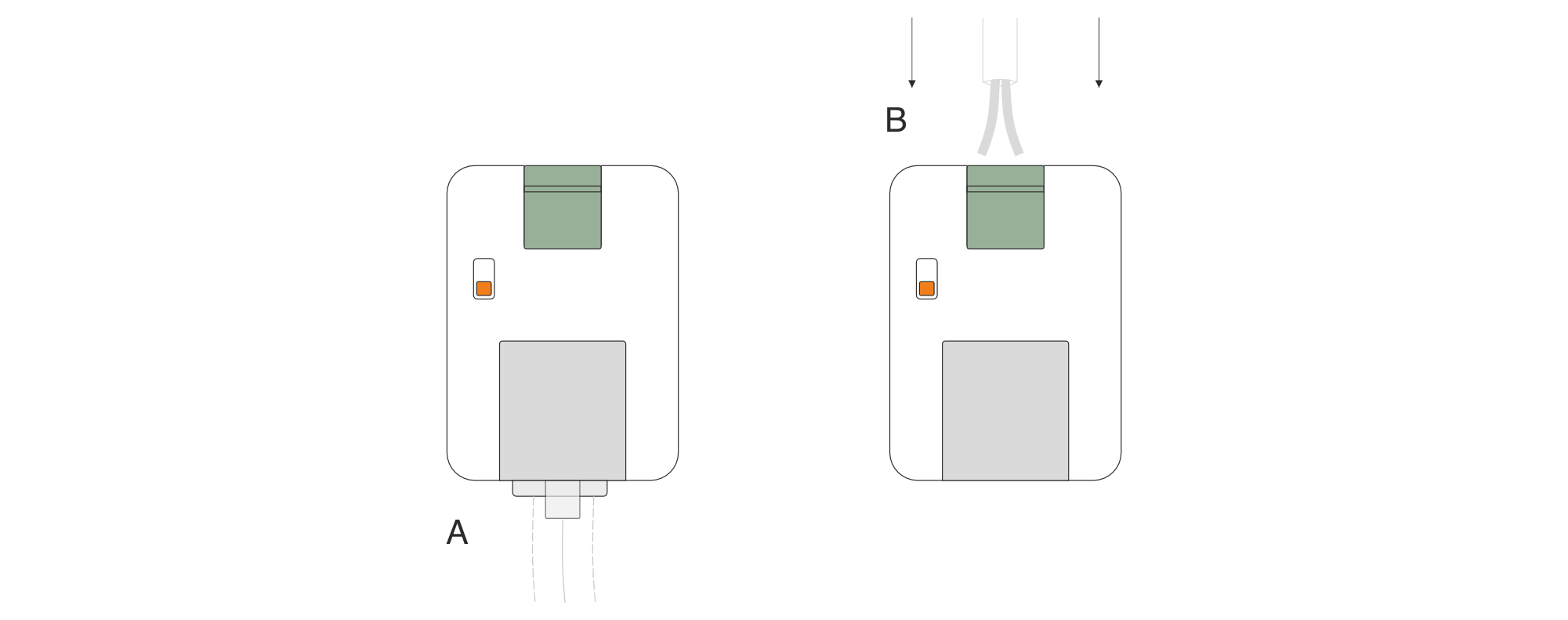
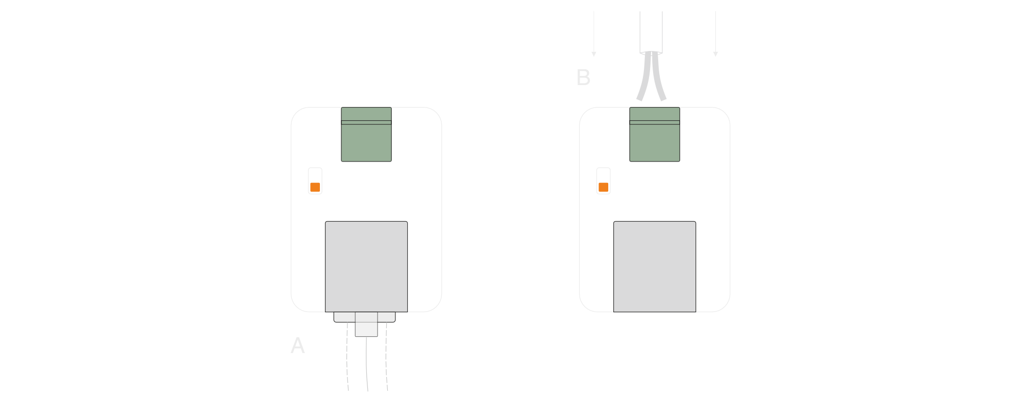
Figure 15. Pulse Input sensor
Configuration
Configurable Parameters
A few parameters must be set before sending data to the gateway. The default firmware is configured in OTAA mode with predefined deveui, appkey (OTAA) and appskey, nwkskey (ABP).
Configuration of the device is stored in a JSON file divided into the following sections:
- info (generic, read only): information about the device,
- lorawan (generic): configuration data for LoRaWAN connection,
- ble (generic): Bluetooth settings,
- device (dynamic): individual configuration for a specific device (this section’s structure differs for each device),
Sample configuration file for the YO Meter Reader device.
{
	"info": {
			"devmodel": "LNMR",
			"fwver": "1.1.4",
			"loraradio": "SX1261",
			"lorawanver": "1.0.2",
			"loraregion": "EU868",
			"blemacaddr": "0123456789ab"
	},
	"lorawan": {
			"subband": 1,
			"nwktype": "public",
			"acttype": "otaa",
			"otaa": {
					"deveui": "0123456789abcdef",
					"appeui": "be7a000000000688",
					"appkey": "000102030405060708090a0b0c0d0e0f",
					"trials": 3
			},
			"abp": {
					"devaddr": "01234567",
					"nwkskey": "0123456789abcdef0123456789abcdef",
					"appskey": "000102030405060708090a0b0c0d0e0f"
			}
	},
	"ble": {
			"power": 0,
			"interval": 1600
	},
	"device": {
			"measinterval": 3600,
			"leddetector": {
					"impkwh": 1000,
					"clearcnt": "no",
					"pulsetime": 10,
					"activeledtimer": 1,
					"lightthreshold": 50
			},
			"opticalinterface": {
					"baudrate": "auto"
			},
			"pulseInput": {
					"debouncetime": 10,
					"impperunit": 1000,
					"activeledtimer": 1,
					"clearcnt": "no"
			}
	}
}
OTAA & ABP
| OTAA | ABP |
|---|---|
| Device EUI | Device Address |
| Application EUI | Network Session Key |
| Application Key | Application Session Key |
| Number of Trials |
Generic Parameters
Click here to see the generic parameters for Yosensi devices.
Parameters
Device Parameters
| Name | Description | Possible Values | Default Value | Read/Write |
|---|---|---|---|---|
| measinterval | Measuring and sending interval LoRa [s] | 601-999999 | 3600 | R/W |
| ||||
Parameters description
- nwktype: used for setting the device in public or private network type.
- acttype: used for setting the device in ABP or OTAA mode.
- deveui, … , appskey: predefined addresses and keys, these parameters are generated using multiple IDs specific to the particular MCU and are unique for each device. They can be changed if needed.
- interval: determines the interval of sending broadcast packets, used to connect to every BLE receiver around the device.
- subband: used for setting the communication frequency sub-band in LoRaWAN.
- measinterval: measurement interval [s] between sending LoRa packets.
LED Pulse Sensor Parameters
| Name | Description | Possible Values | Default Value | Read/Write |
|---|---|---|---|---|
| lightthreshold | LED detection pulse threshold [lx] | 0–107374 | 200 | R/W |
| pulsetime | Integration time of LED pulse counter [ms] | 1–999999 | 20 | R/W |
| impkwh | Utilities (energy, water, gas) consumption [kWh], [J], [m3]... | 1–999999 | 1000 | R/W |
| activeledtimer | Timer of active LED indicator [h] | 0–24 | 1 | R/W |
| clearcnt | Clear the persistent pulse counter | no, yes | no | R/W |
Parameters description
- lightthreshold: used to set the light threshold [lx] for the LED pulse counter sensor.
- pulsetime: integration time [ms] of LED pulse counter. Parameter determine maximum frequency for LED pulse counter.
- impkwh: determines calculation of Total units payload measurement. It calculates the units based on the measured impulses based on the following formula: Total units = (Persistent counter)/impkwh.
- activeledtimer: determines the timer of active LED indicator in LED pulse counter sensor. Expressed in hours. Can be deactivated by setting value equals 0.
- clearcnt: device keeps a persistent counter in EEPROM where it stores the total number of pulses counted; this counter can be cleared using this parameter.
Pulse Input Sensor Parameters�
| Name | Description | Possible Values | Default Value | Read/Write |
|---|---|---|---|---|
| debouncetime | Debounce time [ms] | 0–9999 | 10 | R/W |
| impperunit | Impulses per unit | 1–999999 | 1000 | R/W |
| activeledtimer | Timer of active LED indicator [h] | 0–24 | 1 | R/W |
| clearcnt | Clear the persistent pulse counter | no, yes | no | R/W |
Parameters description
- lightthreshold: used to set the light threshold [lx] for the LED pulse counter sensor.
- pulsetime: integration time [ms] of LED pulse counter. Parameter determine maximum frequency for LED pulse counter.
- impperunit: determines calculation of Total units payload measurement.
- activeledtimer: determines the timer of active LED indicator in Pulse Input counter sensor. Expressed in hours. Can be deactivated by setting value equals 0.
- clearcnt: device keeps a persistent counter in EEPROM where it stores the total number of pulses counted; this counter can be cleared using this parameter.
IEC 62056-21 Interface Sensor Parameters
| Name | Description | Possible Values | Default Value | Read/Write |
|---|---|---|---|---|
| baudrate | Communication data speed | Auto, 9600, 4800, 2400, 1200, 600, 300 | auto | R/W |
Parameters description
- baudrate: used to set the optical sensor data communication speed - some utilities meters work with lower speed.
Downlink message
You can remotely adjust certain parameters by sending a downlink message through our platform. Simply navigate to the "COMMANDS" section for the selected device.
Change Measurement Interval
It is possible to change the measurement interval (measinterval) by using downlink. Information about changing the parameter will be sent from the server via the gateway.
Example of Downlink Message:
- Prefix:
0x03 - Measurement Index:
0x00 - Data (up to 4 bytes in hex):
0258
Sample Downlink: 0x03000258 - Sets a measurement interval of 600 seconds (10 minutes).
Click here to see how to connect a node using the Yosensi Management Platform.
See how to configure a node in Yosensi Management Platform
Check how to adopt and configure a node via the Yosensi App.
Take a look at the list of frequency plans used in Yosensi.
This datasheet describes the payload protocol developed by Yosensi for communicating with our devices.
Payload Decoder
If you want to connect to your own server, it is necessary to decode the specific payload for each device. To accomplish this, a payload decoder is required, which can be downloaded using the following link: Payload decoder. You can also use our integrated Payload Decoder here. Extended documentation of the protocol can be found in the Payload description on our website.
Compliance Statements
To view or download the Declaration of Conformity for YO Meter Reader 2.0 go here