YO Temp
Overview
Description
YO Temp is a LoRaWAN device for measuring temperature at up to three external points. It also includes temperature and humidity sensors, providing environmental context around the device's location for informational purposes.
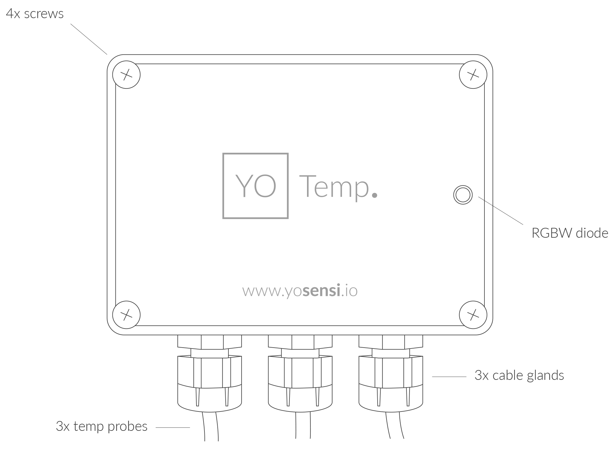
Figure 1. Device top view
Device sticker placed on the right side of the device enclosure contains information about model, version, LoRaWAN region and 3 parameters important in case of device identification and configuration:
- DEV EUI: 64-bit unique device identifier in a LoRaWAN network,
- DEV ADDR: address required to connect via ABP activation type to LoRaWAN,
- BLE MAC: Bluetooth physical address.
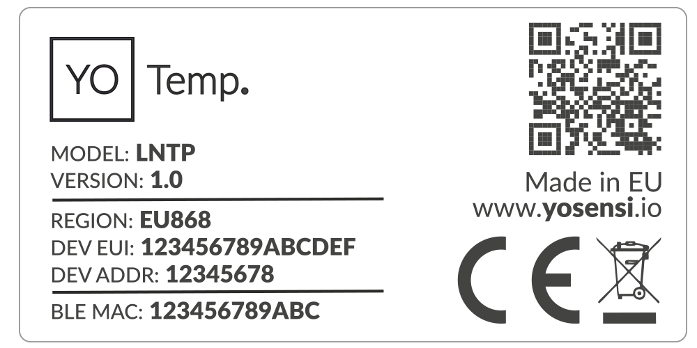
Figure 2. Device sticker
Features
- LoRaWAN Technology: Available in multiple versions with LoRa radio configured for various regions and ISM frequency bands (e.g., EU868, US915, AU915), it is compatible with both private and public LoRaWAN networks and supports connections via ABP (Activation by Personalization) or OTAA (Over-The-Air Activation).
- Bluetooth Low Energy (BLE): Enables easy configuration through a user-friendly JSON data exchange format, supports firmware updates via OTA (Over-the-Air), and boasts very low energy consumption.
- Battery-Powered: 3x AA lithium batteries featuring very low self-discharge, ensuring long-term operation without the need for an external power supply.
- Temperature and Relative Humidity: Measures temperature and relative humidity within the device enclosure, providing valuable insights into the surrounding environment.
- External Temperature: Measure external temperatures with precision and versatility using up to three connected probes, ideal for a wide range of monitoring applications.
- Yosensi Management Platform: Provides a web tool for device configuration, firmware updates, and infrastructure management. Enables comprehensive monitoring of transmitted data and easy device management.
- Yosensi Mobile App: Effortlessly manage devices with features to register new ones, configure settings, perform firmware updates, view/send logs, and test LoRaWAN connectivity. Learn more in our detailed Yosensi App blog post.
Specifications
Physical
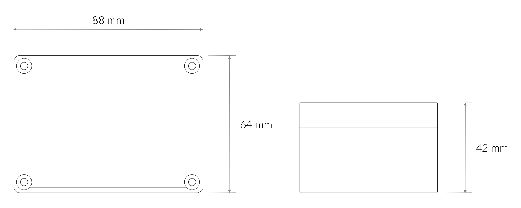
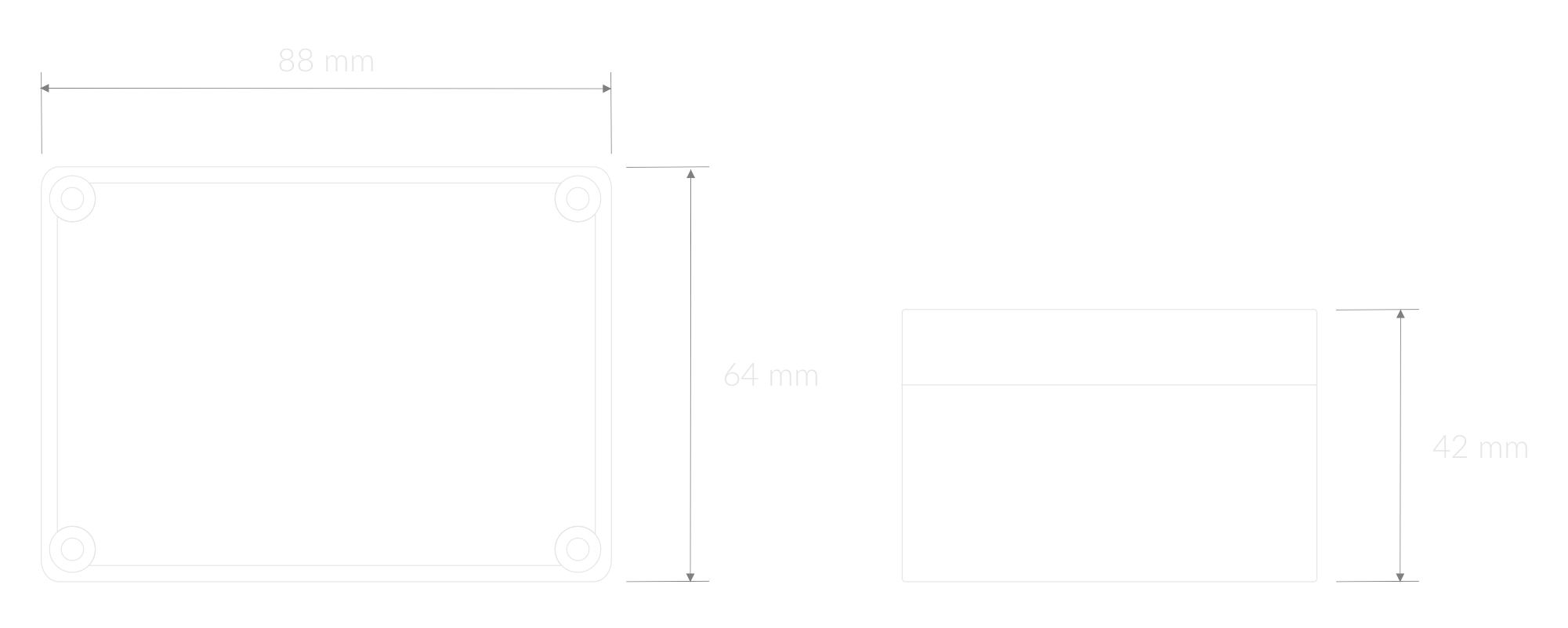
Figure 3. Dimensions of the device
Device
| Attribute | Description |
|---|---|
| Dimensions | Height: 42 mm Width: 88 mm Depth: 64 mm |
| Colour | Light Grey |
| Mounting method | Horizontal Vertical (can be screwed to the wall) |
| Enclosure material | ABS |
| Level of protection | IP67, IK09 |
| Weight (without batteries, excl. probes) | 200 g |
Temperature sensor
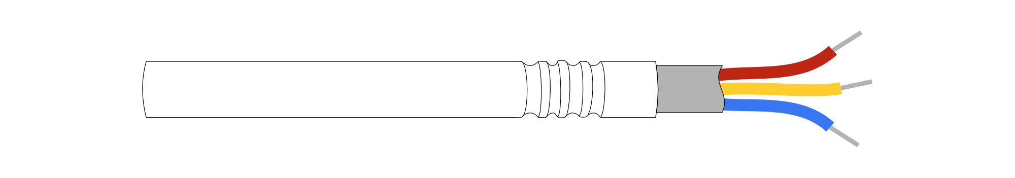
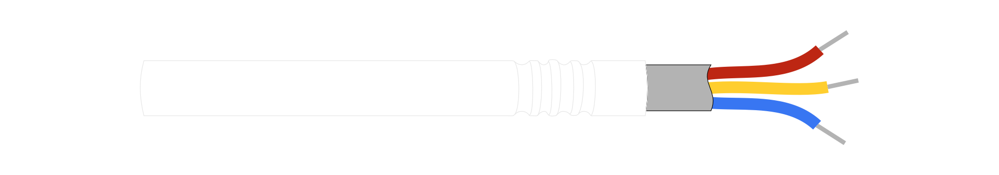
Figure 4. Temperature sensor
| Attribute | Description |
|---|---|
| Dimensions | 6 mm x 51 mm |
| Colour | Silver/Red |
| Cable lengths | 1 m, 2 m, 3 m, 5 m, 10 m |
| Weights | 30 g, 60 g, 90 g, 180 g, 290 g |
Operating Conditions
| Attribute | Description |
|---|---|
| Temperature | 0°C to 70°C |
| Humidity | 0 to 90% |
| Placement | Indoor use |
| Power supply | 3 x LR6 (AA) battery (3 x 1.5 V) |
| Power consumption | Maximum: 120 mA DC (4.5 V DC) |
Measured Values
| Parameter | Measurement range | Accuracy |
|---|---|---|
| Temperature (internal) | -40°C to 125°C | ±0.2°C (5°C to 60°C) |
| Relative humidity (internal) | 0% to 100% | ±2% (20% to 80%) |
| External temperature sensor | -55°C to 125°C | ±0.5°C (from -10°C to 85°C) |
Controls and Indicators
LED Status Indicator
YO Temp communicates its current behaviour to the user by RGBW LED placed on the top.
Diode statuses interpretation
| Behavior | Colour | Status |
|---|---|---|
| Single flash | Green | General: device is working correctly (power and memory). |
| Single flash | Red | General: device is working incorrectly (power and memory). LoRaWAN communication: failed to receive an acknowledgement from LoRaWAN Server within specified timeout. |
| Single flash | White | LoRaWAN communication: LoRaWAN frame sent / confirmation from LoRaWAN Server after receiving the frame. |
| Slow flashing | Blue | BLE communication: connection to the device via BLE (configuration). |
| Rapid flashing | Blue | LoRaWAN communication: connecting to LoRaWAN network. |
Buttons
The YO Temp has a button for resetting the device. Figure 5 shows its placement. To reboot the device, press the reset button for a moment.
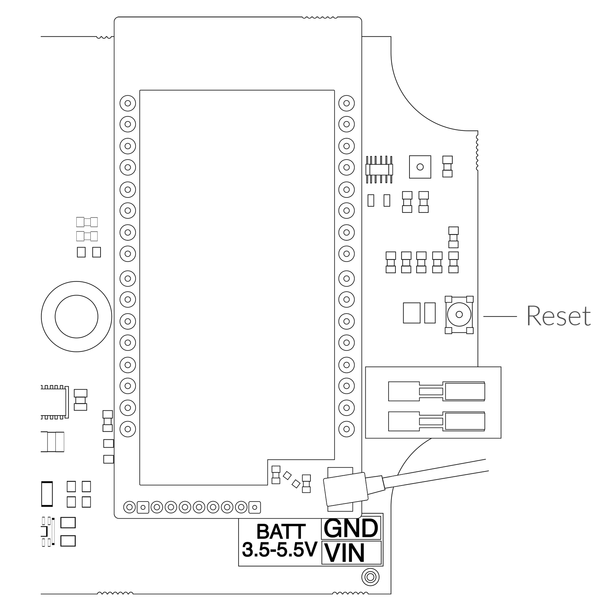
Figure 5. Reset button
Installation
Package Contents
- Device (without batteries).
- PG7 cable gland cap - 3pcs.
- Warranty card.
Safety Precautions
Go to the Safety Precautions section to see important information on handling, disposal and maintenance.
Installation Guide
- Unscrew the device: remove 4 screws from the enclosure.
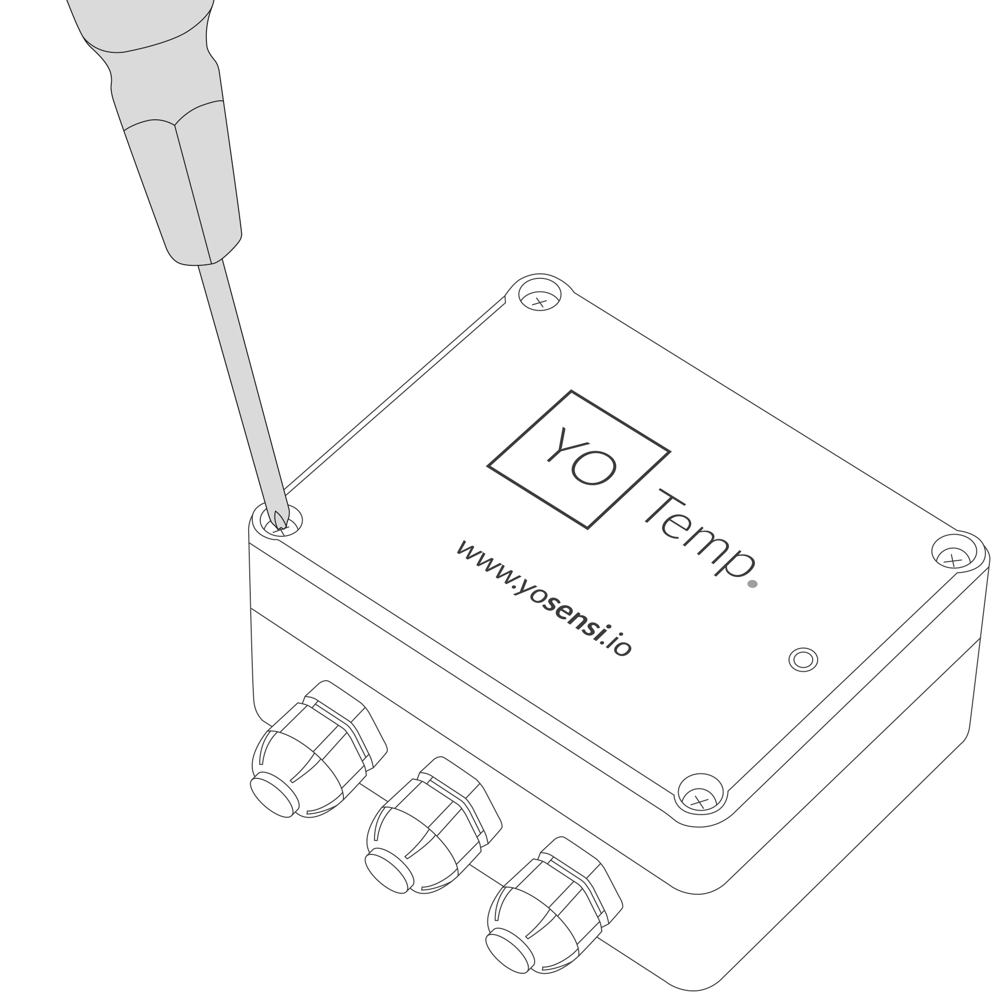
Figure 6. Device opening instructions
- Unscrew the cable gland nut and remove the cap.
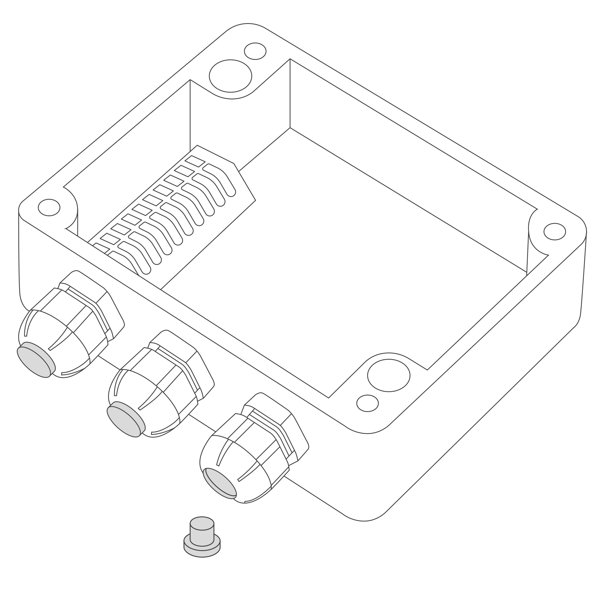
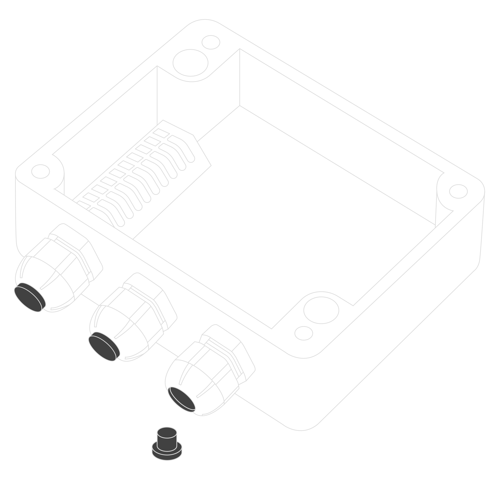
Figure 7. Unscrew the cable gland nut and remove the cap
- Pull the temperature sensor through the cable gland. You can connect one, two or three external temperature sensors as required.
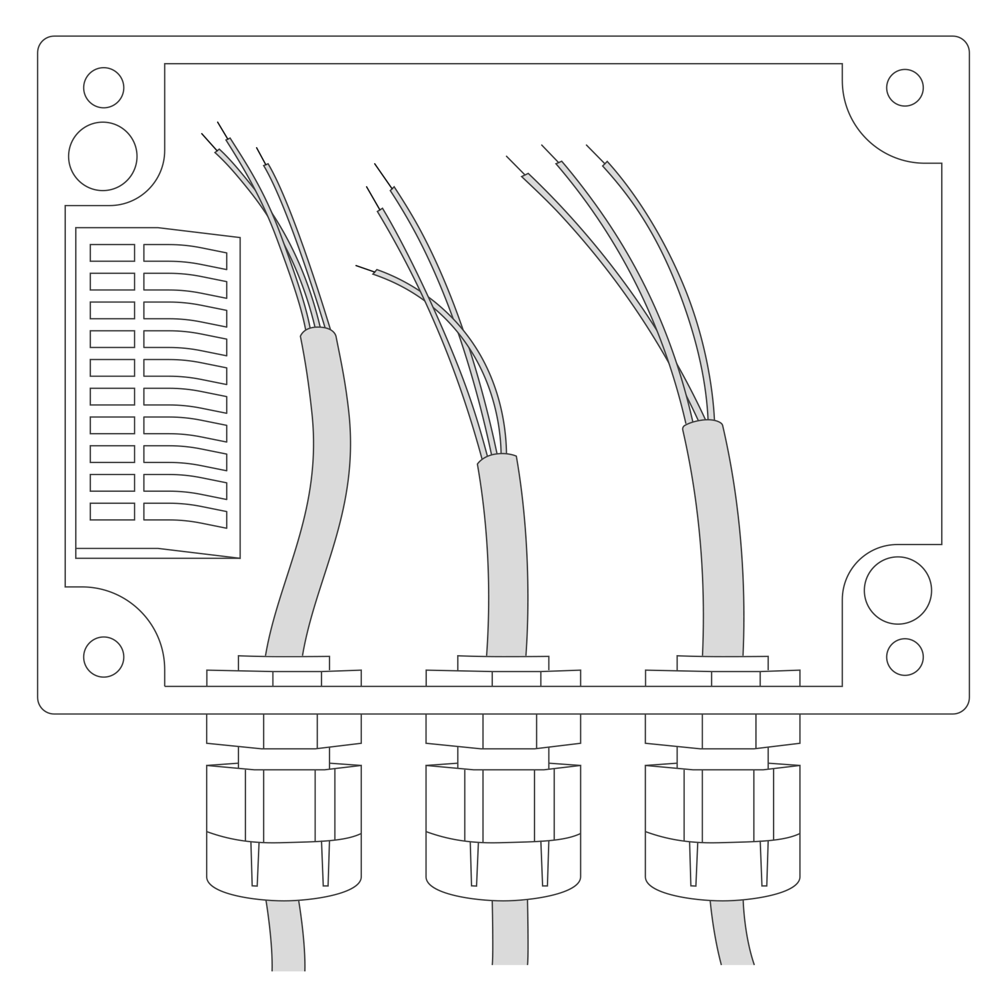
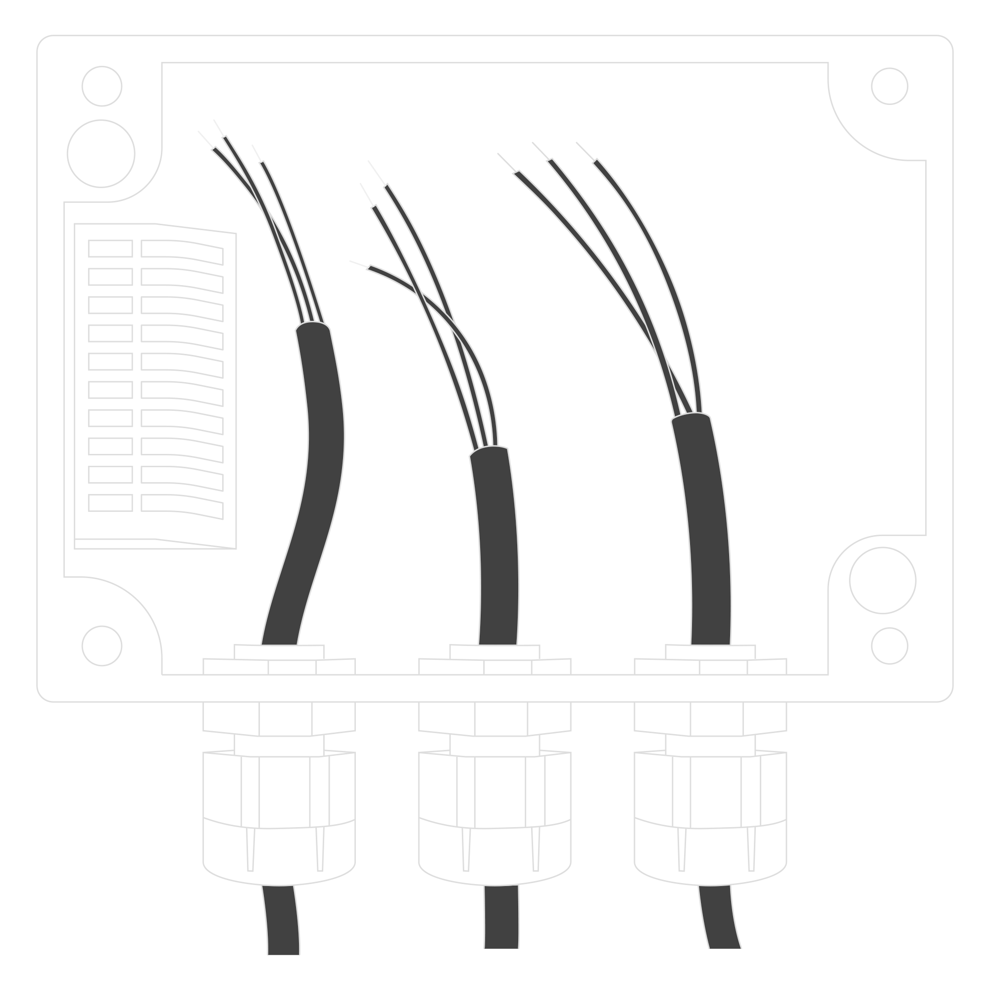
Figure 8. Input cable passing through the cable gland instructions
-
Pull the temperature sensor through the cable gland. Press the spring contact and insert the appropriate wire into the corresponding slot in the connector:
- GND - black or blue wire (depending on the batch)
- DATA - yellow wire
- VCC - red wire
Tighten the cable gland to immobilise the external sensor wires and maintain tightness.
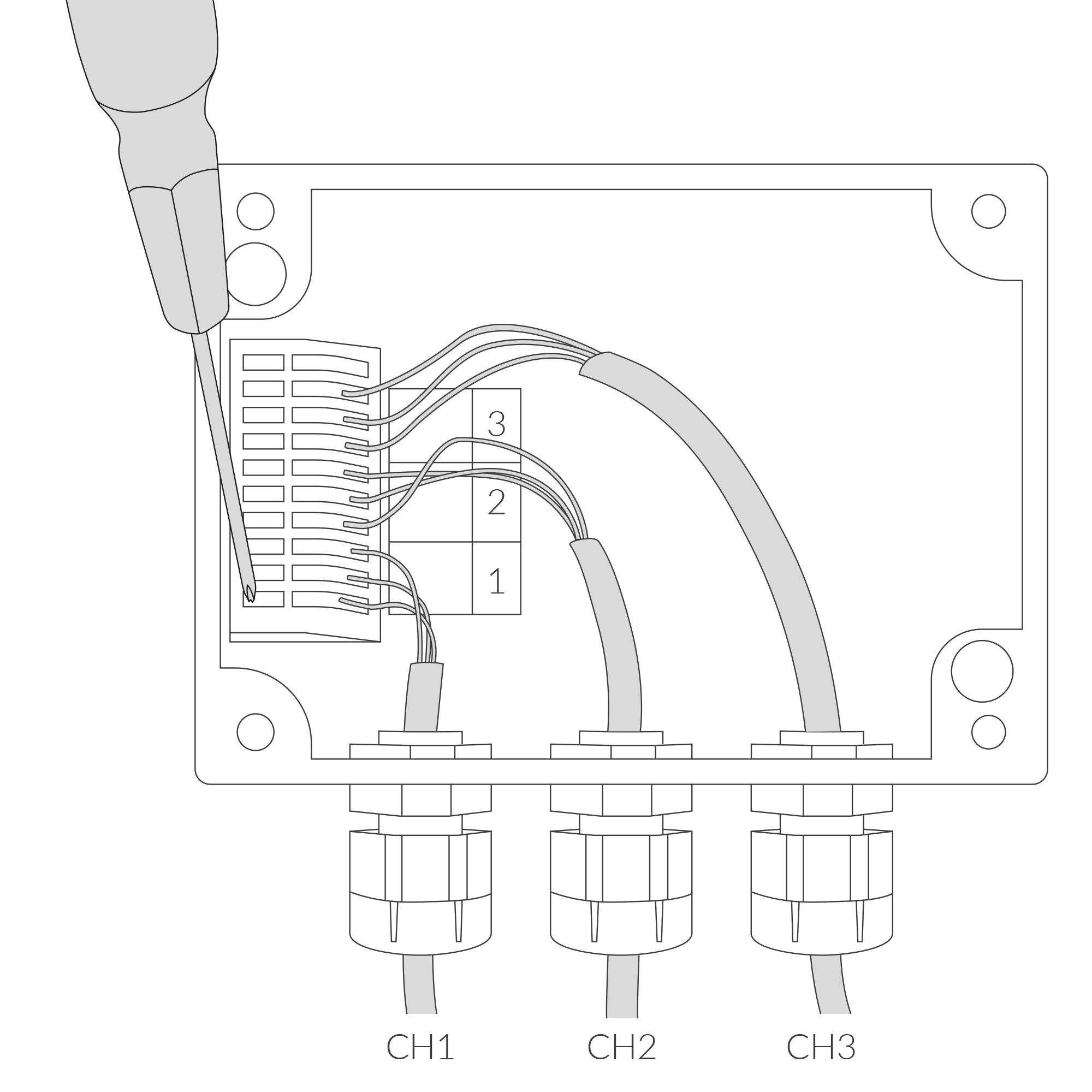
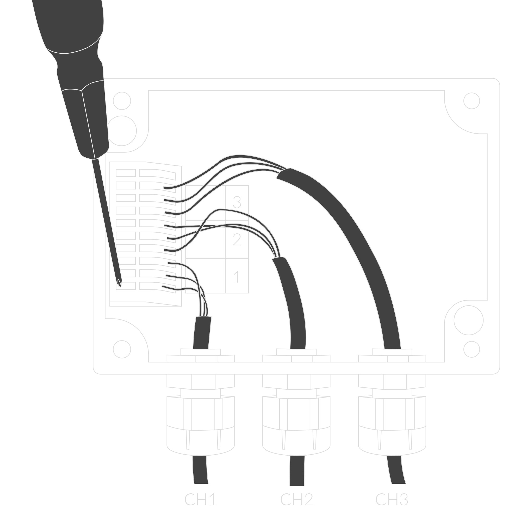
Figure 9. Connecting input cable instructions
- Place three LR6 batteries in the device according to the polarity indicated on the battery holder.
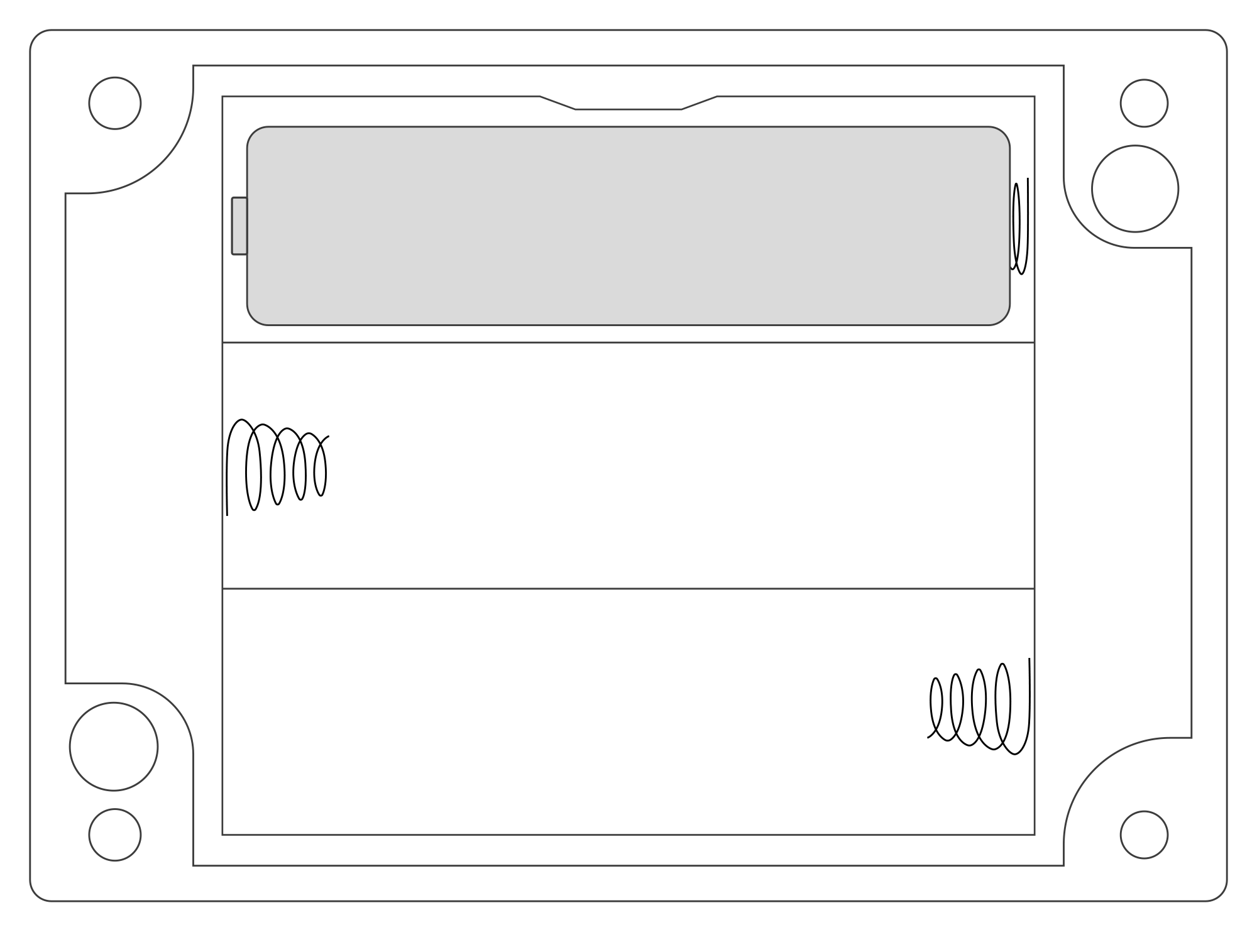
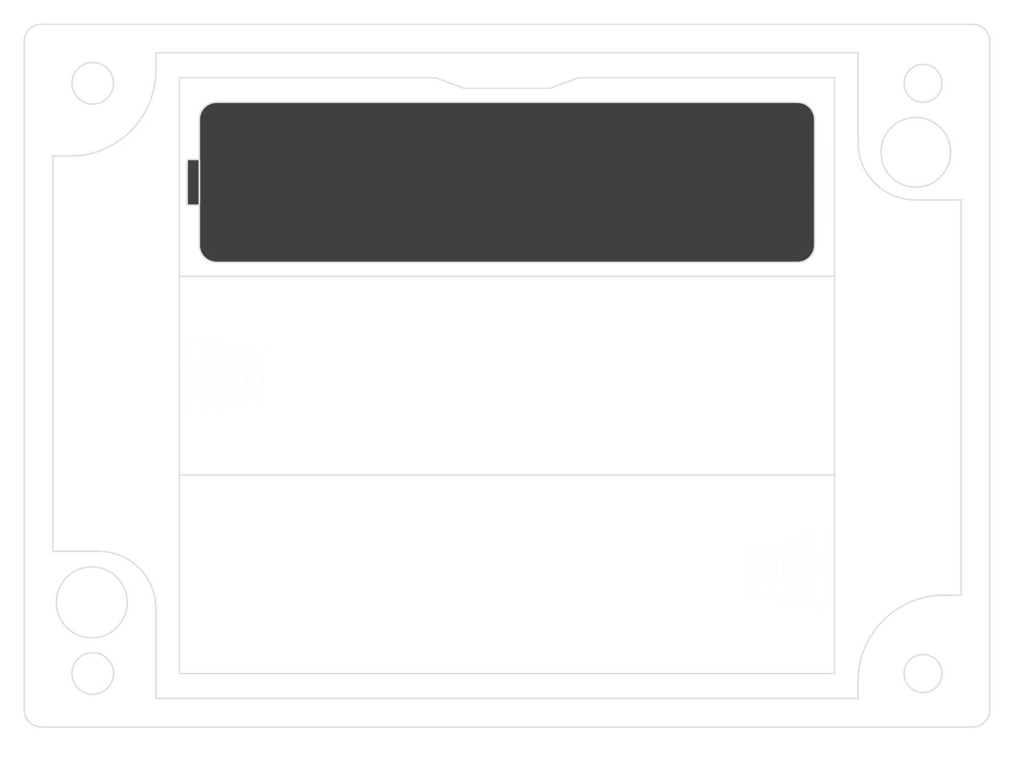
Figure 10. Battery placement instructions
- Assemble the device and screw it back together.
Configuration
Configurable Parameters
A few parameters must be set before sending data to the gateway. The default firmware is configured in OTAA mode with predefined deveui, appkey (OTAA) and appskey, nwkskey (ABP).
Configuration of the device is stored in a JSON file divided into the following sections:
- info (generic, read only): information about the device,
- lorawan (generic): configuration data for LoRaWAN connection,
- ble (generic): Bluetooth settings,
- device (dynamic): individual configuration for a specific device (this section’s structure differs for each device),
Sample configuration file for the YO Temp device.
{
	"info": {
		"devmodel": "LNTP",
		"fwver": "3.6.1",
		"loraradio": "SX1261",
		"lorawanver": "1.0.2",
		"loraregion": "EU868",
		"blemacaddr": "0123456789ab"
	},
	"lorawan": {
		"subband": 1,
		"nwktype": "public",
		"acttype": "otaa",
		"otaa": {
			"deveui": "0123456789abcdef",
			"appeui": "fedcba9876543210",
			"appkey": "000102030405060708090a0b0c0d0e0f",
			"trials": 3
		},
		"abp": {
			"devaddr": "01234567",
			"nwkskey": "0123456789abcdef0123456789abcdef",
			"appskey": "000102030405060708090a0b0c0d0e0f"
	}
	},
	"ble": {
		"power": 0,
		"interval": 1600
	},
	"device": {
		"measinterval": 1800
	}
}
OTAA & ABP
| OTAA | ABP |
|---|---|
| Device EUI | Device Address |
| Application EUI | Network Session Key |
| Application Key | Application Session Key |
| Number of Trials |
Generic Parameters
Click here to see the generic parameters for Yosensi devices.
Parameters
Device Parameters
| Name | Description | Possible Values | Default Value | Read/Write |
|---|---|---|---|---|
| measinterval | Measuring and sending interval LoRa [s] | 601-999999 | 1800 | R/W |
| ||||
Parameters description
- nwktype: used for setting the device in public or private network type.
- acttype: used for setting the device in ABP or OTAA mode.
- deveui, … , appskey: predefined addresses and keys, these parameters are generated using multiple IDs specific to the particular MCU and are unique for each device. They can be changed if needed.
- interval: determines the interval of sending broadcast packets, used to connect to every BLE receiver around the device.
- subband: used for setting the communication frequency sub-band in LoRaWAN.
- measinterval: measurement interval [s] between sending LoRa packets.
Downlink message
You can remotely adjust certain parameters by sending a downlink message through our platform. Simply navigate to the "COMMANDS" section for the selected device.
Update Measurement Interval
It is possible to change the measurement interval (measinterval) by using downlink. Information about changing the parameter will be sent from the server via the gateway.
Example of Downlink Message:
- Prefix:
0x03 - Measurement Index:
0x00 - Data (up to 4 bytes in hex):
0258
Sample Downlink: 0x03000258 - Sets a measurement interval of 600 seconds (10 minutes).
Click here to see how to connect a node using the Yosensi Management Platform.
See how to configure a node in Yosensi Management Platform
Check how to adopt and configure a node via the Yosensi App.
Take a look at the list of frequency plans used in Yosensi.
This datasheet describes the payload protocol developed by Yosensi for communicating with our devices.
Payload Decoder
If you want to connect to your own server, it is necessary to decode the specific payload for each device. To accomplish this, a payload decoder is required, which can be downloaded using the following link: Payload decoder. You can also use our integrated Payload Decoder here. Extended documentation of the protocol can be found in the Payload description on our website.
Compliance Statements
To view or download the Declaration of Conformity for YO Temp go here