YO People Counter
Overview
Description
The YO People Counter is a bi-directional device utilizing a cutting-edge 24 GHz radar transceiver to simultaneously detect motion from both directions. It can independently identify individuals when a minimum distance is maintained between them, making it ideal for accurately counting foot traffic in buildings, exhibitions, and airports. For optimal performance, the device should be installed near building entrances and in narrow corridors. It is not recommended to place the device in locations with nearby moving objects, such as sliding doors, as this could interfere with its field of view.

Figure 1. Device top view
Device sticker placed on the right side of the device enclosure contains information about model, version, LoRaWAN region and 3 parameters important in case of device identification and configuration:
- DEV EUI: 64-bit unique device identifier in a LoRaWAN network,
- DEV ADDR: address required to connect via ABP activation type to LoRaWAN,
- BLE MAC: Bluetooth physical address.
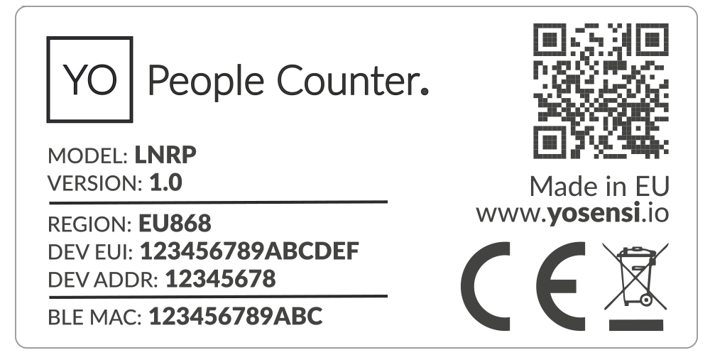
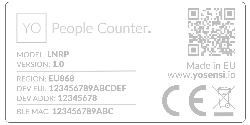
Figure 2. Device sticker
Features
- LoRaWAN Technology: Available in multiple versions with LoRa radio configured for various regions and ISM frequency bands (e.g., EU868, US915, AU915), it is compatible with both private and public LoRaWAN networks and supports connections via ABP (Activation by Personalization) or OTAA (Over-The-Air Activation).
- Bluetooth Low Energy (BLE): Enables easy configuration through a user-friendly JSON data exchange format, supports firmware updates via OTA (Over-the-Air), and boasts very low energy consumption.
- Temperature and Relative Humidity: Measures temperature and relative humidity within the device enclosure, providing valuable insights into the surrounding environment.
- Radar: Operates at 24 GHz with an 80°/34° beam aperture and a range of 10–500 cm.
- Bi-directional counting: Accurately captures and monitors the flow of people or objects moving left-to-right and right-to-left using radar-based detection.
- Flow analysis and net count: Sums and compares counts from both directions to provide the total flow of people, indicating the net difference between those entering and leaving the monitored area.
- Yosensi Management Platform: Provides a web tool for device configuration, firmware updates, and infrastructure management. Enables comprehensive monitoring of transmitted data and easy device management.
- Yosensi Mobile App: Effortlessly manage devices with features to register new ones, configure settings, perform firmware updates, view/send logs, and test LoRaWAN connectivity. Learn more in our detailed Yosensi App blog post.
Specifications
Physical
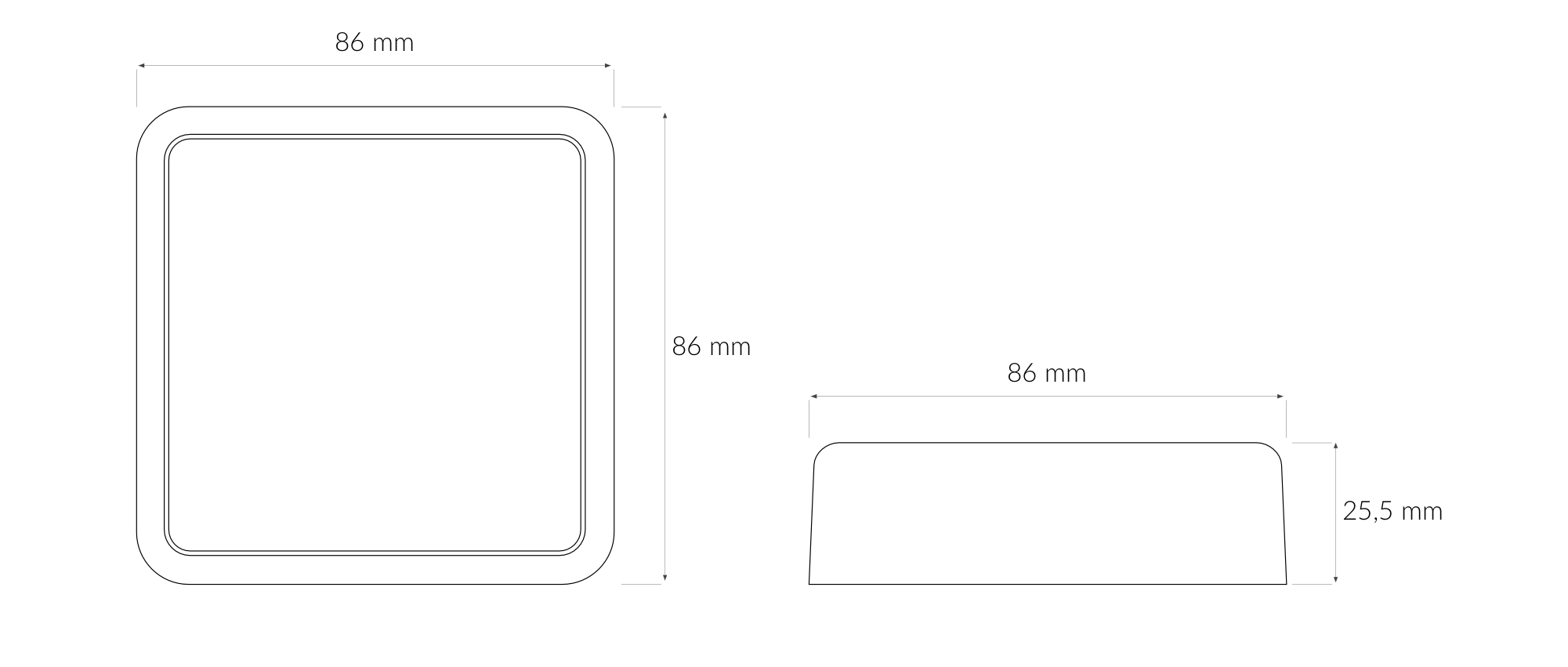
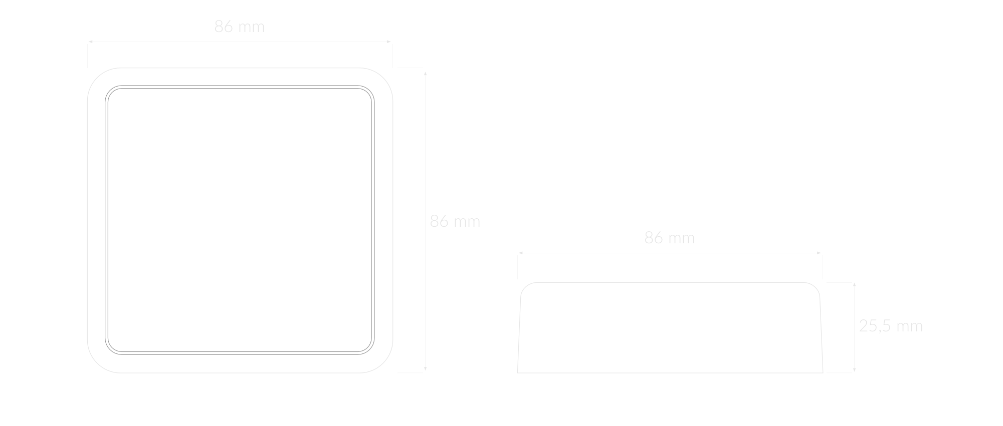
Figure 3. Dimensions of the device
Device
| Attribute | Description |
|---|---|
| Dimensions | Height: 25.5 mm Width: 86 mm Depth: 86 mm |
| Colour | White |
| Mounting method | Horizontal Vertical (can be screwed to the wall) |
| Enclosure material | ABS |
| Level of protection | IP40, UL94-V0 |
| Weight | 91 g (without batteries) |
Operating Conditions
| Attribute | Description |
|---|---|
| Temperature | 0°C to 70°C |
| Humidity | 0 to 90% |
| Placement | Indoor use |
| Power supply | USB-C 5 V DC 6-30 V DC 5 - 21 V AC |
| Power consumption | Maximum: 1.1A (12 V DC) |
Measured Values
| Parameter | Measurement range | Accuracy |
|---|---|---|
| Temperature (internal) | -40°C to 125°C | ±0.2°C (5°C to 60°C) |
| Relative humidity (internal) | 0% to 100% | ±2% (20% to 80%) |
| Left-to-right counter | 0-2147483647 ( int32 ) | - |
| Right-to-left counter | 0-2147483647 ( int32 ) | - |
| Sum-of-left-to-right counts | 0-2147483647 ( int32 ) | - |
| Sum-of-right-to-left counts | 0-2147483647 ( int32 ) | - |
| Difference between sum counts | 0-2147483647 ( int32 ) | - |
Controls and Indicators
LED Status Indicator
YO People Counter communicates its current behaviour to the user by RGBW LED placed on top.
Diode statuses interpretation
| Behavior | Colour | Status |
|---|---|---|
| Single flash | Green | General: device is working correctly (power and memory). |
| Single flash | Red | General: device is working incorrectly (power and memory). LoRaWAN communication: failed to receive an acknowledgement from LoRaWAN Server within specified timeout. |
| Single flash | White | LoRaWAN communication: LoRaWAN frame sent / confirmation from LoRaWAN Server after receiving the frame. |
| Slow flashing | Blue | BLE communication: connection to the device via BLE (configuration). |
| Rapid flashing | Blue | LoRaWAN communication: connecting to LoRaWAN network. |
Buttons
The YO People Counter has a button for resetting the device. Figure 4 shows its placement. To reboot the device, press the reset button for a moment.
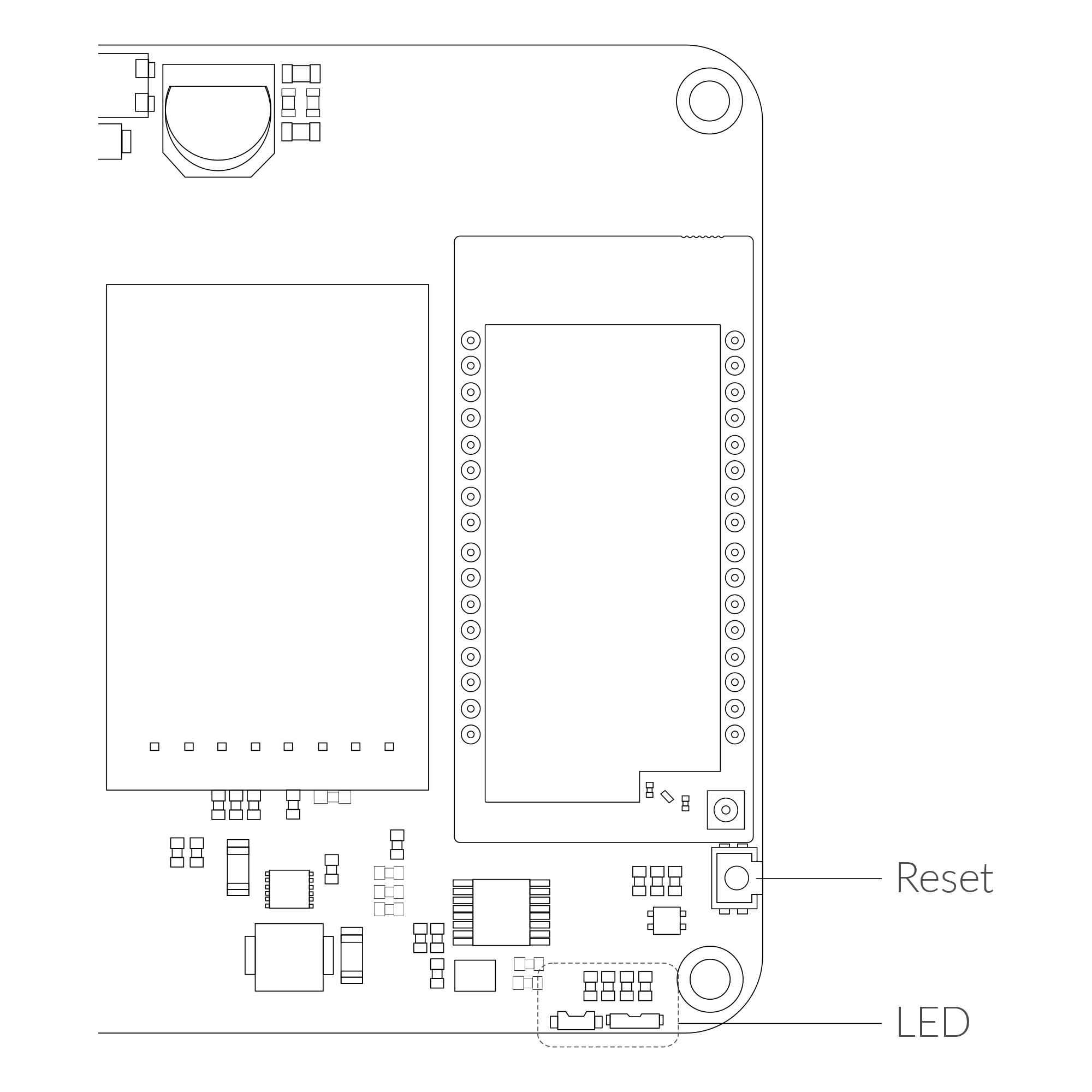
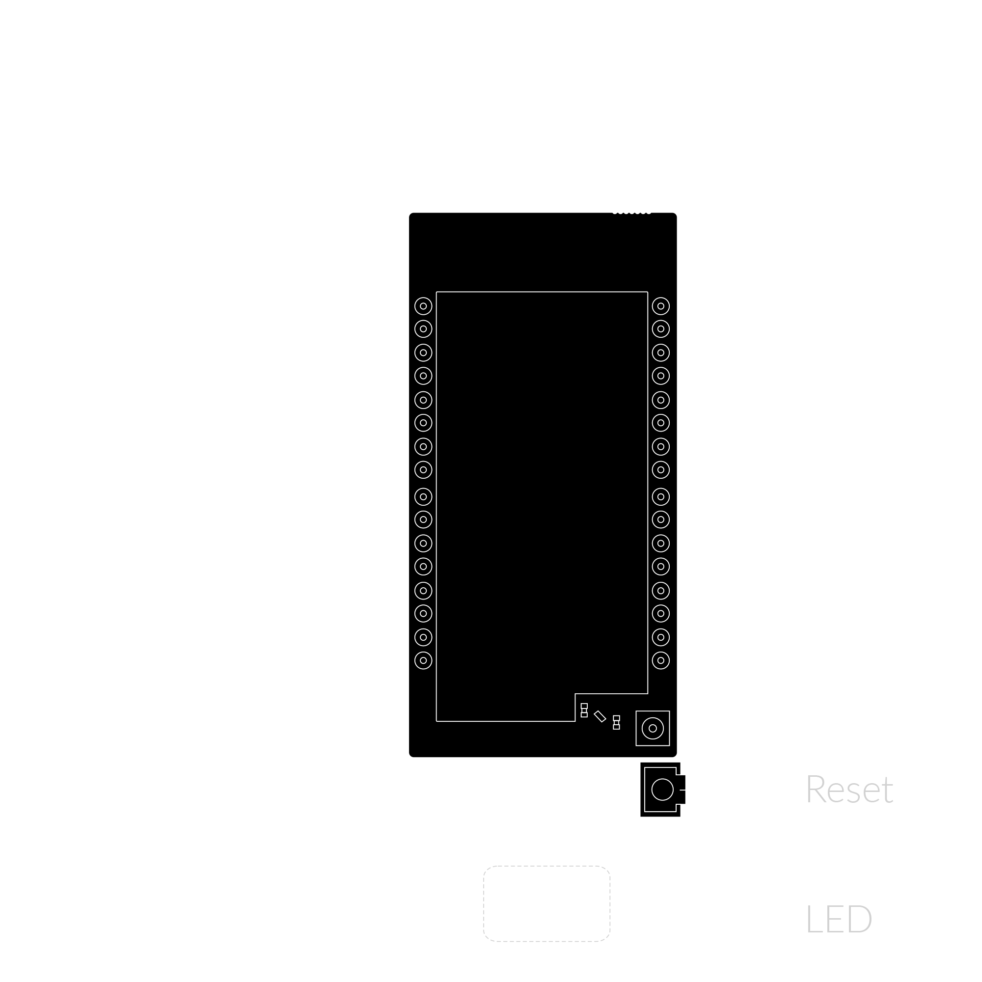
Figure 4. Reset button
Installation
Package Contents
- Device (without batteries).
- Warranty card.
Safety Precautions
Go to the Safety Precautions section to see important information on handling, disposal and maintenance.
Installation Guide
- Important! The direction of detection must be taken into account when mounting the device.
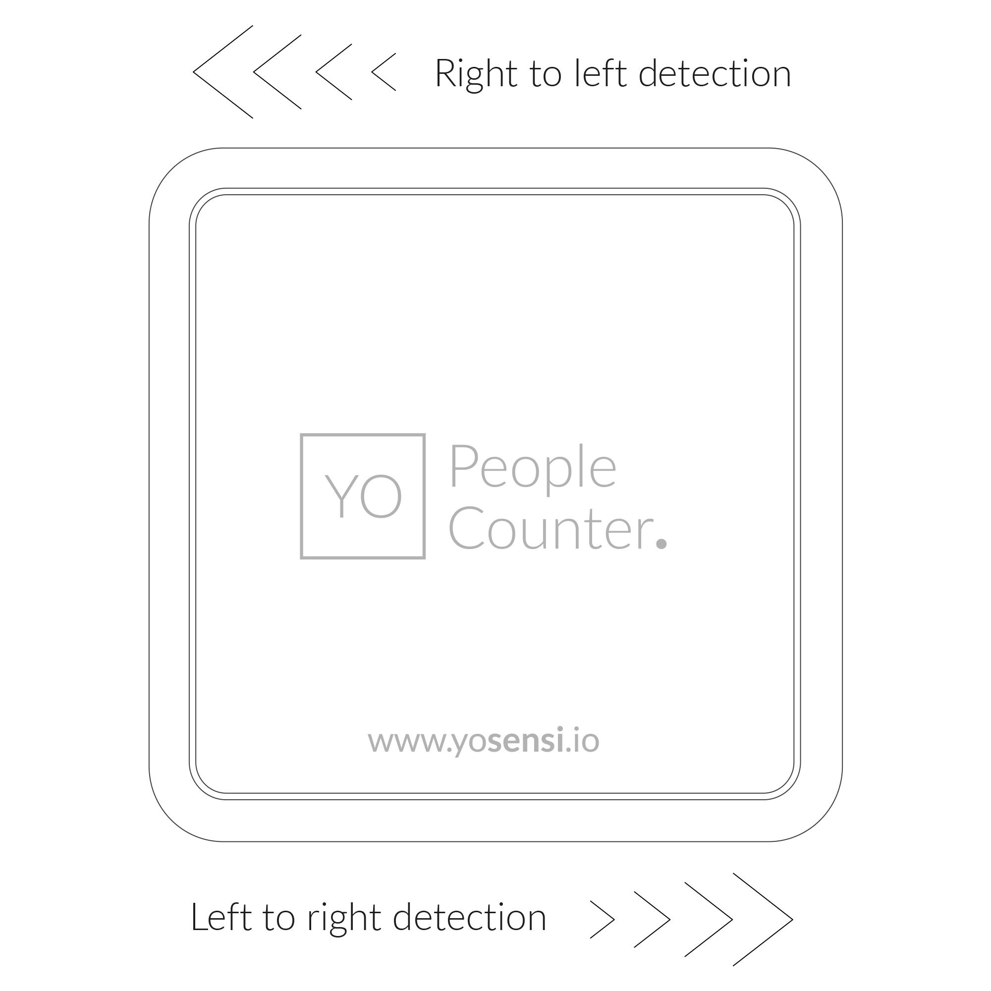
Figure 5. Showing the direction of detection
- To open the enclosure, pry off the lower part.
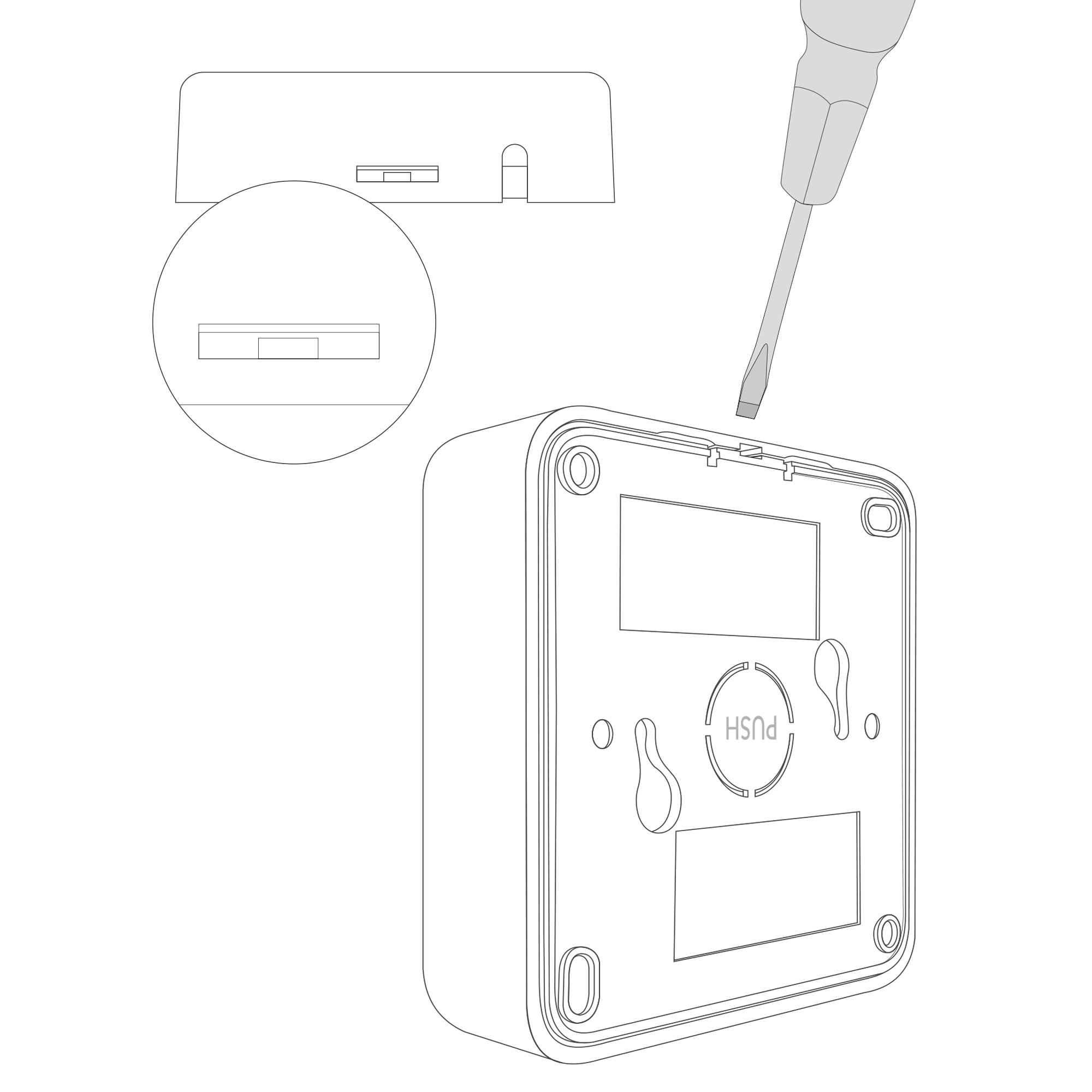
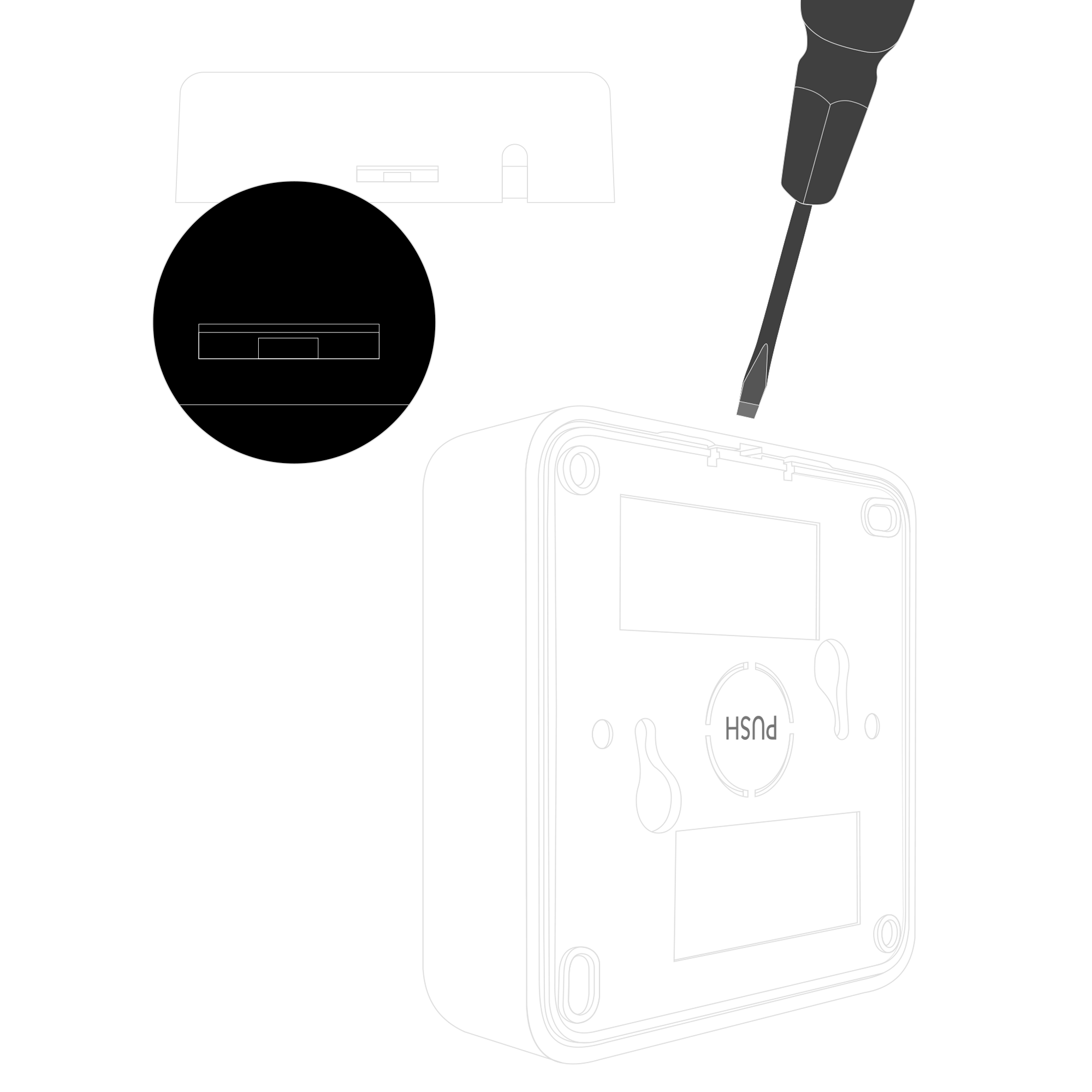
Figure 6. Opening the enclosure of the device
-
YO People Counter can be powered in via USB-C connector, via power supply 6-30 DC or 5-21 AC. There are two ways to connect the device to the power supply.
- A. The user must break the centre plastic circle labelled PUSH out of the mounting bracket before installation.
After that, route the cable through the centre hole of the bracket.
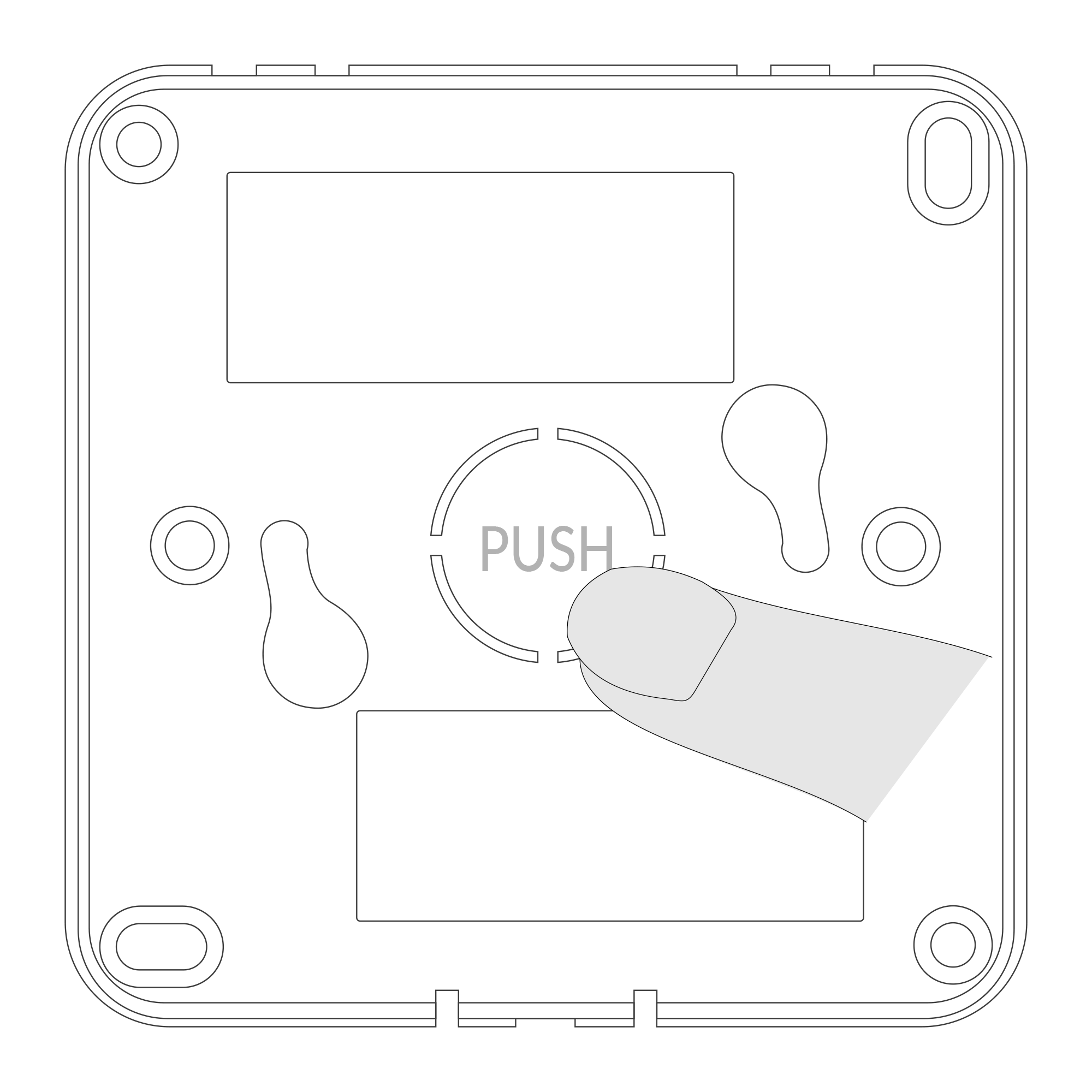
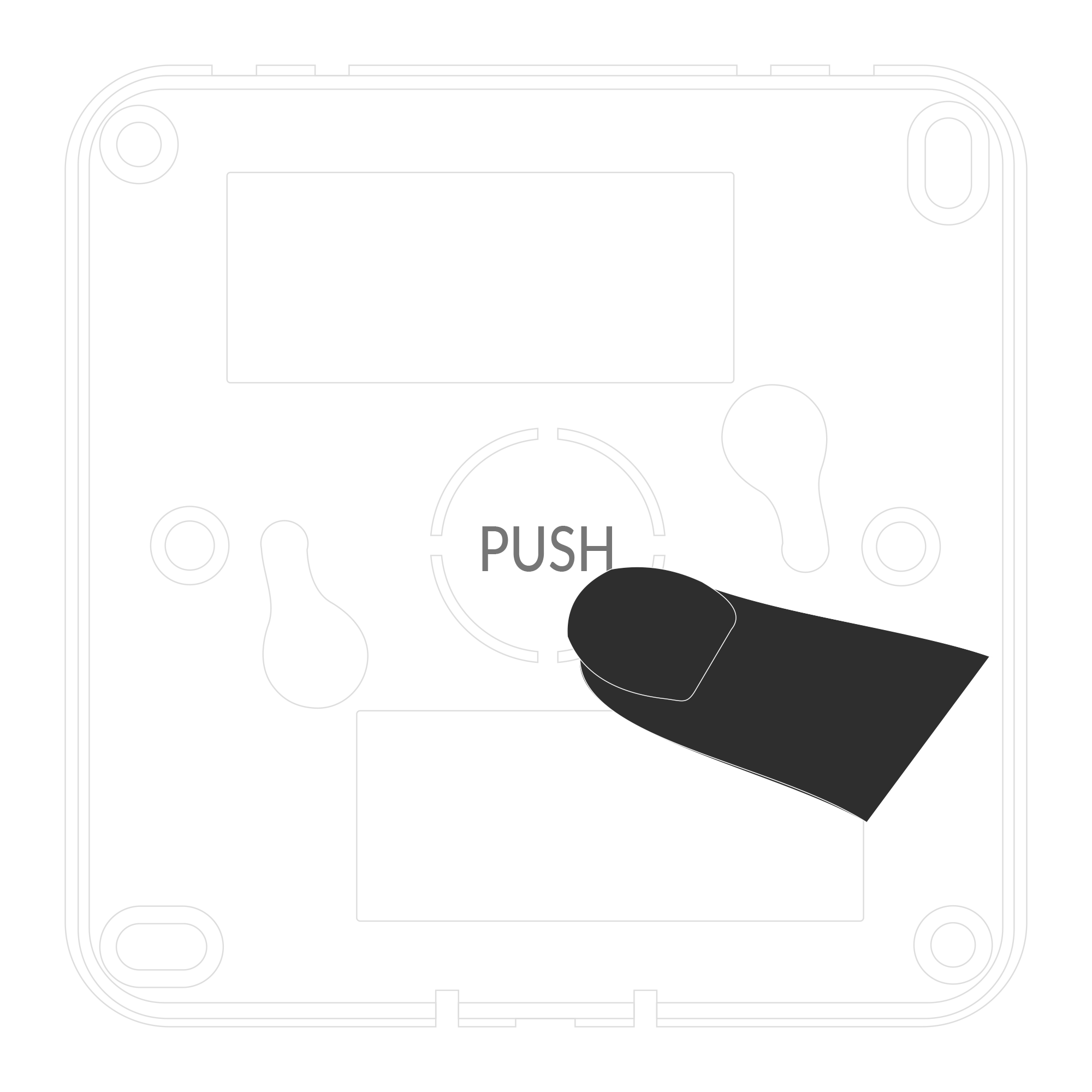
Figure 7. Breaking out the plastic circle labelled PUSH
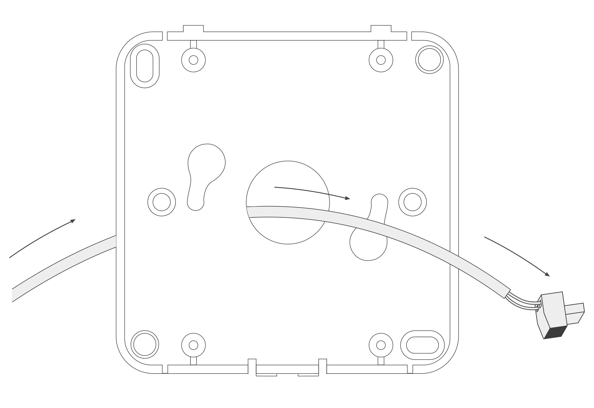
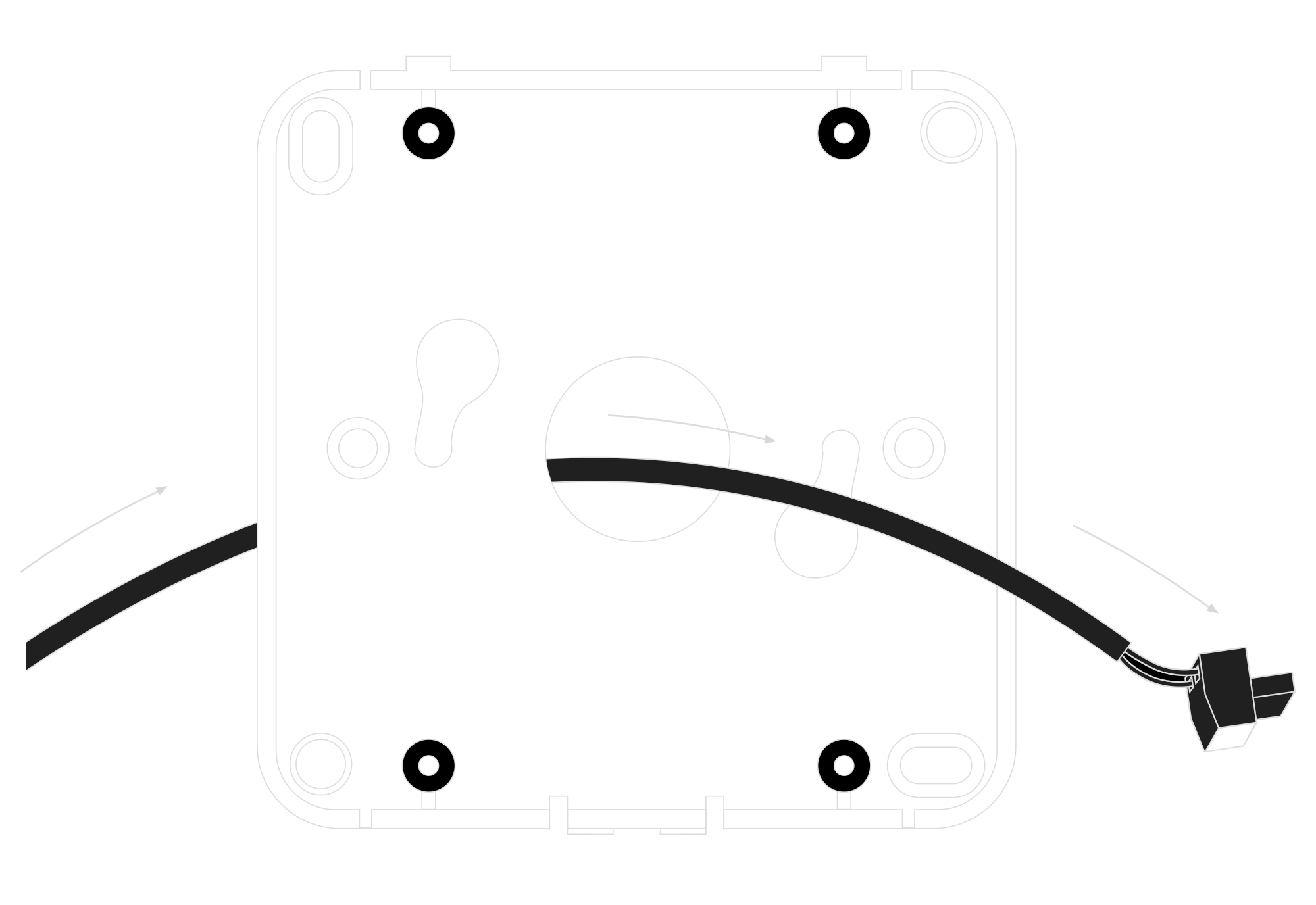
Figure 8. Routing the power supply connector through the centre hole
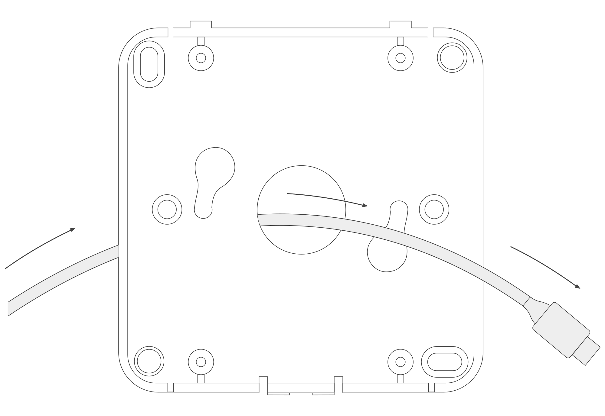
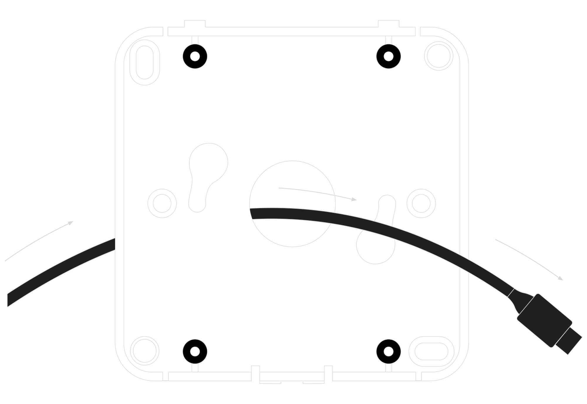
Figure 9. Routing the USB-C cable through the centre hole
- B. The second option is routing the wire through the hole in the mounting bracket. You can route the USB-C cable, 6-30 DC or 5-21 AC power supply cable depending on the supply you need.
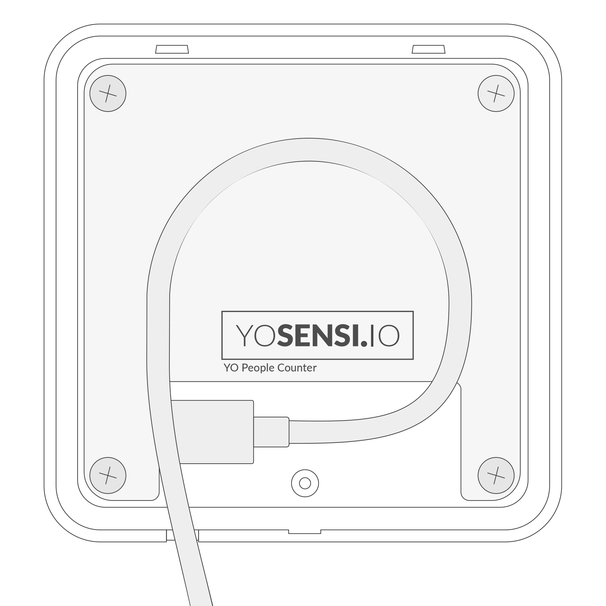
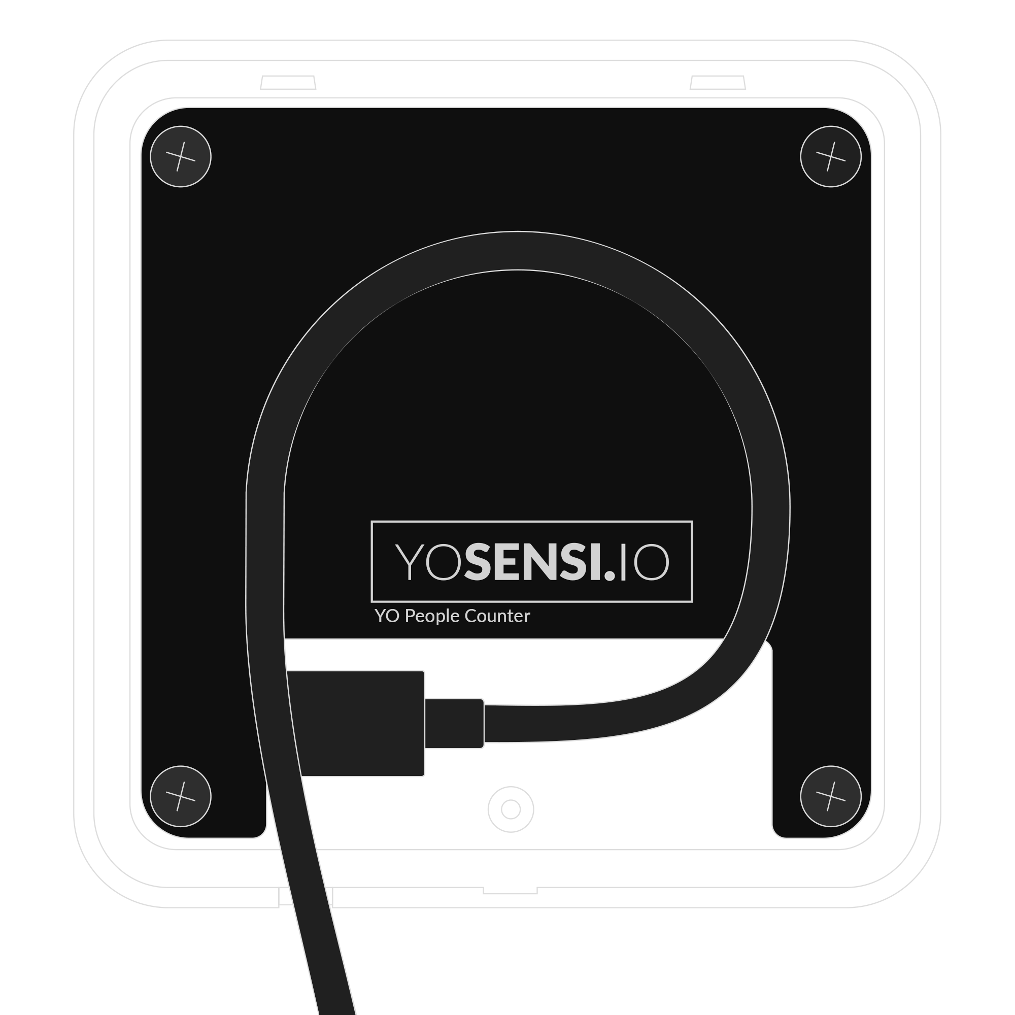
Figure 10. Routing the USB-C cable through the hole in the bottom of the device
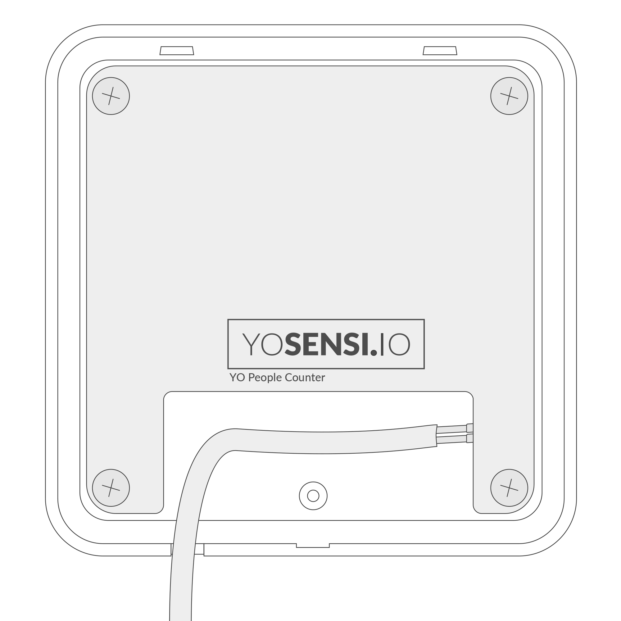
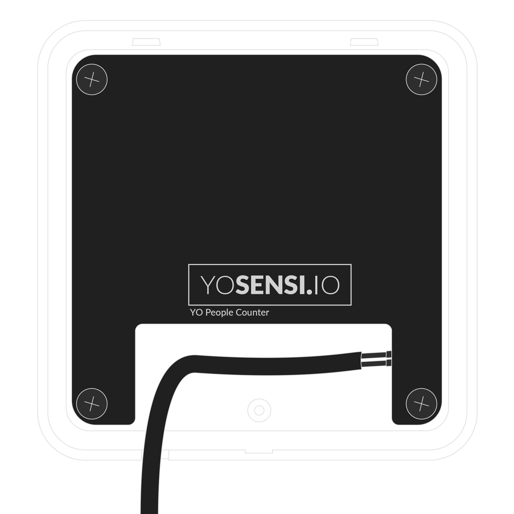
Figure 11. Routing the power supply cable through the hole in the bottom of the device

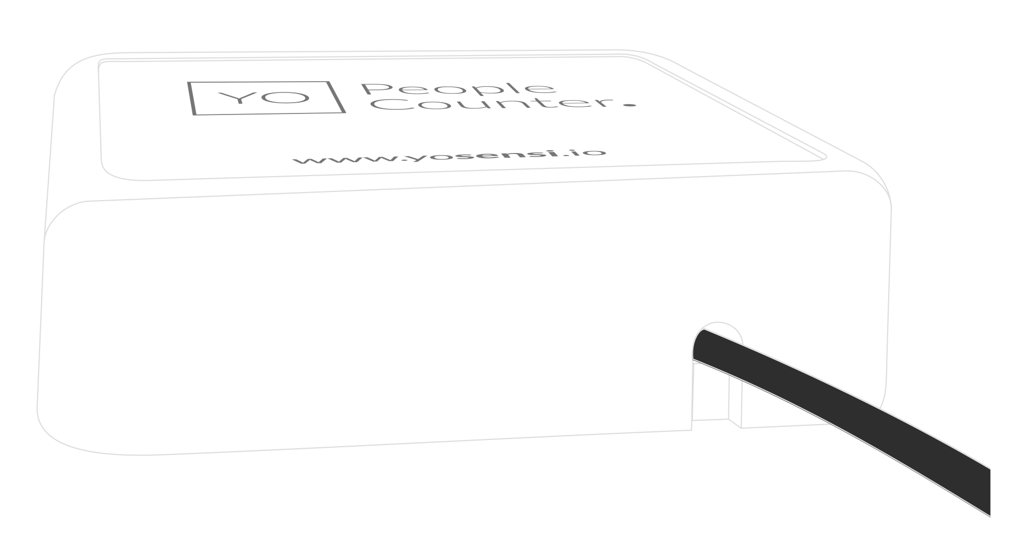
Figure 12. Bottom view of the device after connecting the supply via the bottom hole
- A. The user must break the centre plastic circle labelled PUSH out of the mounting bracket before installation.
After that, route the cable through the centre hole of the bracket.
-
There are two ways to mount the device on a wall.
- A. Install the bottom part of the enclosure and mount four screws in each corner to the wall.
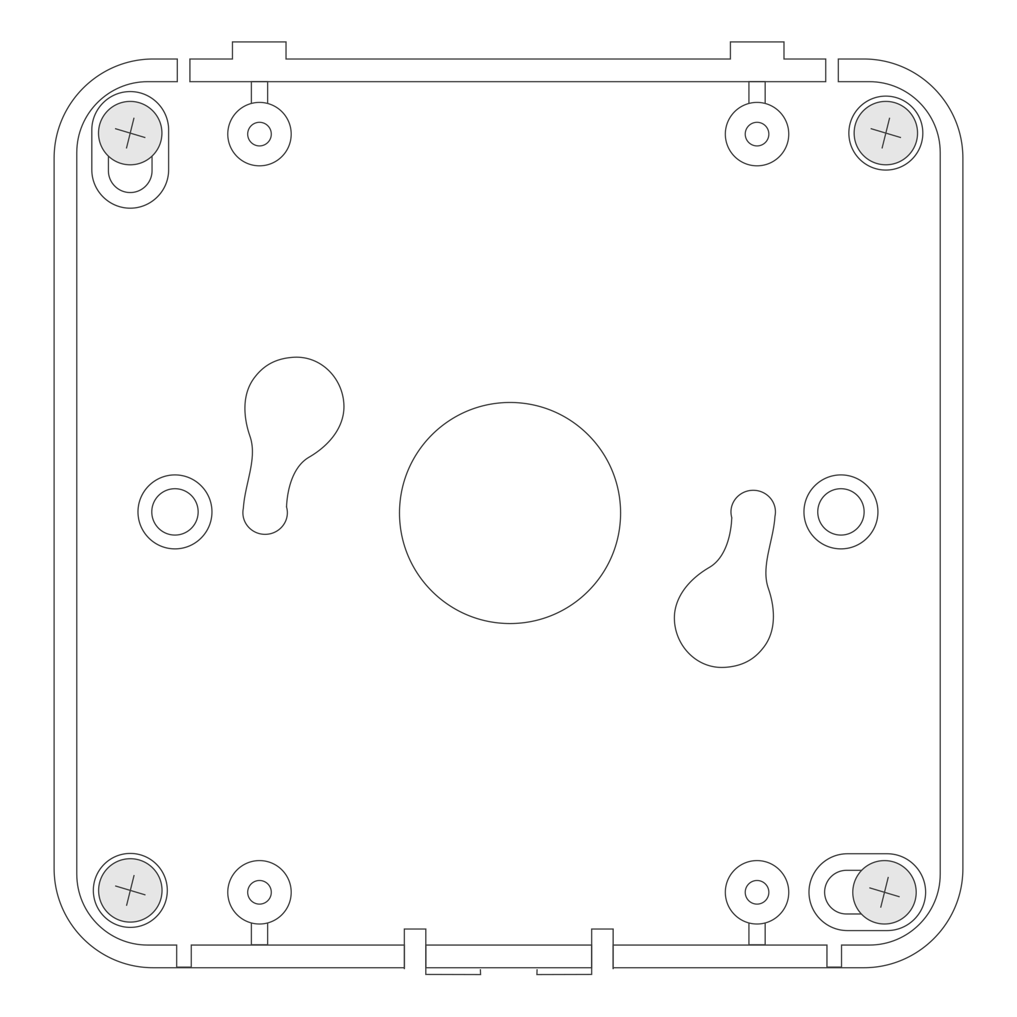
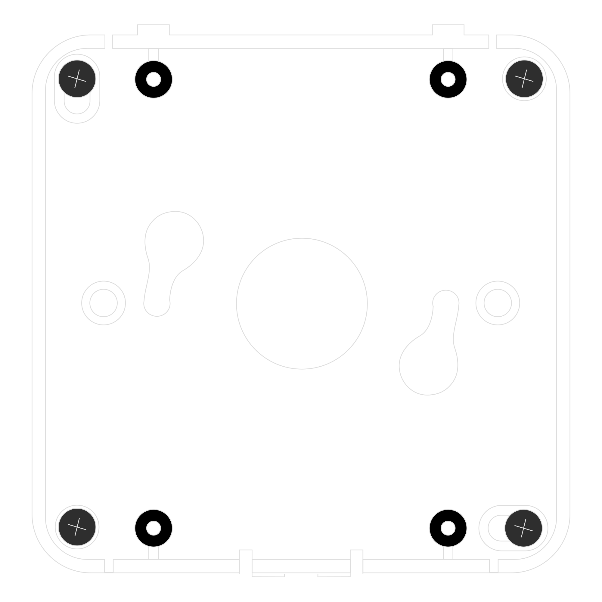
Figure 13. Mounting the device using four screws
- B. Fit two mounting screws into the centre of the bottom case. Then, angle the bottom of the enclosure and turn it clockwise.
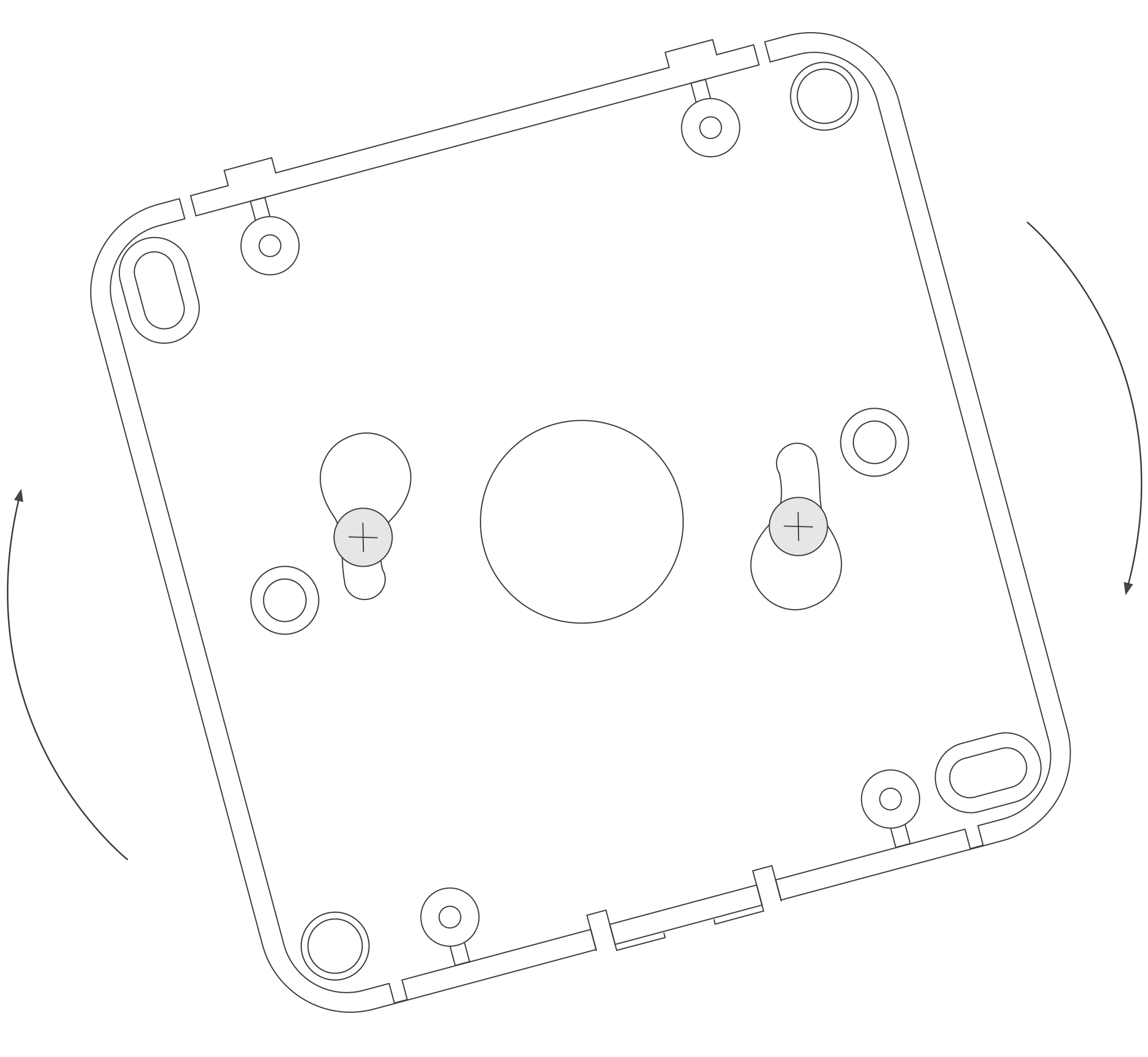
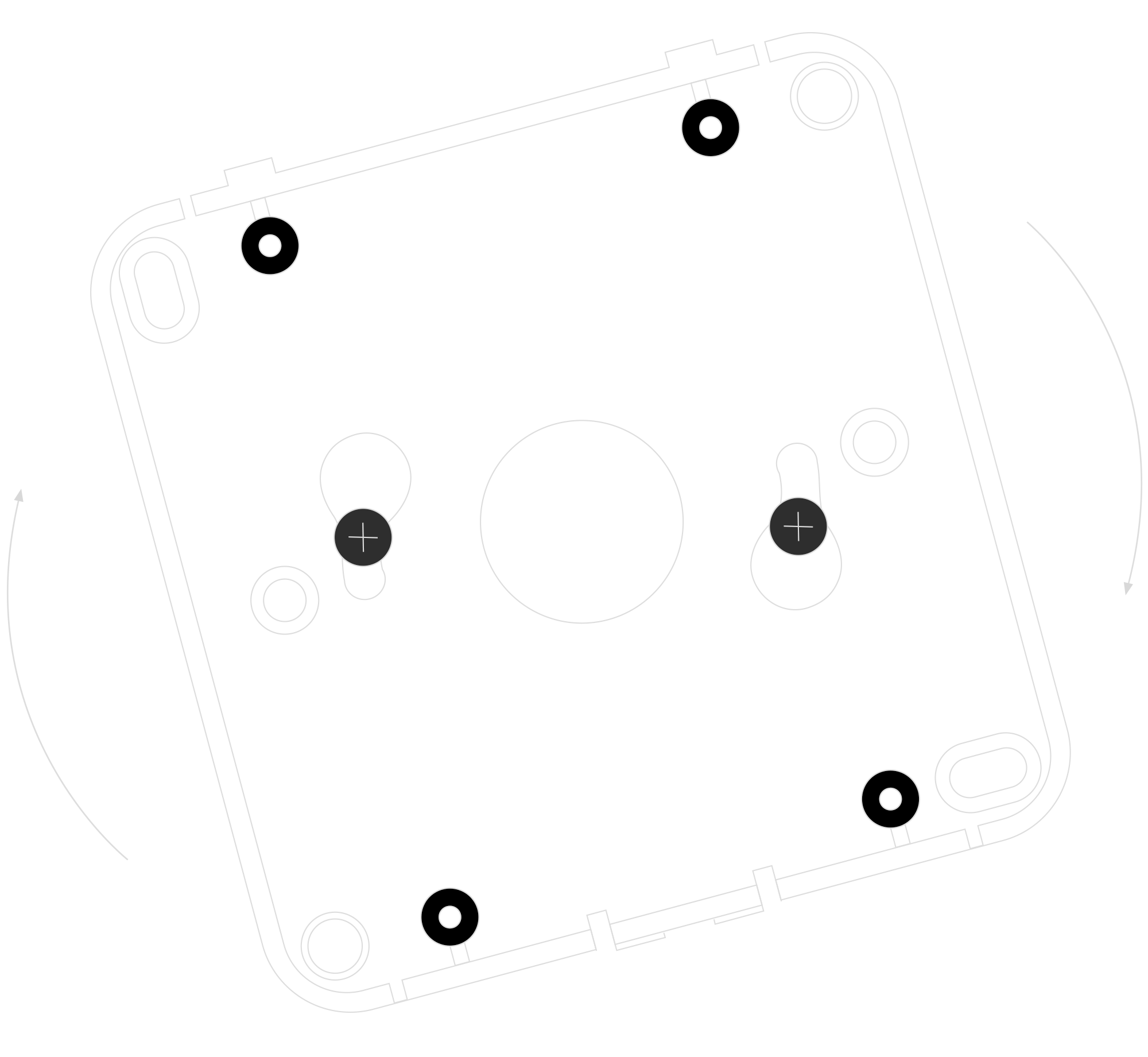
Figure 14. Mounting the device using two screws at an angle
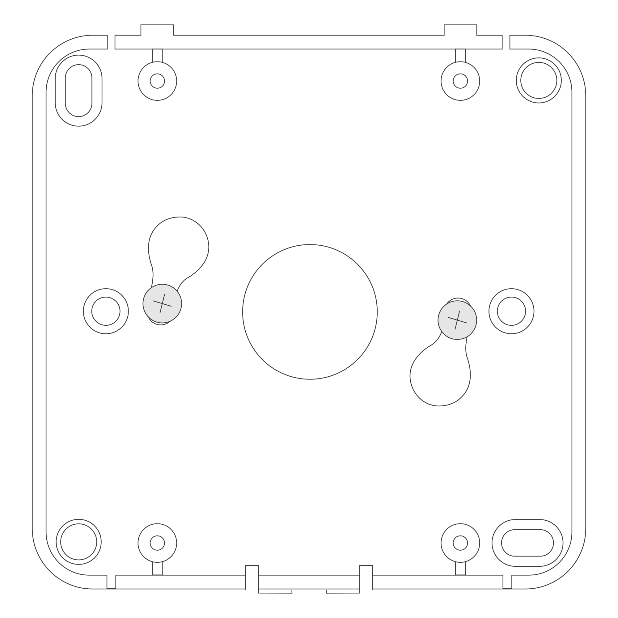
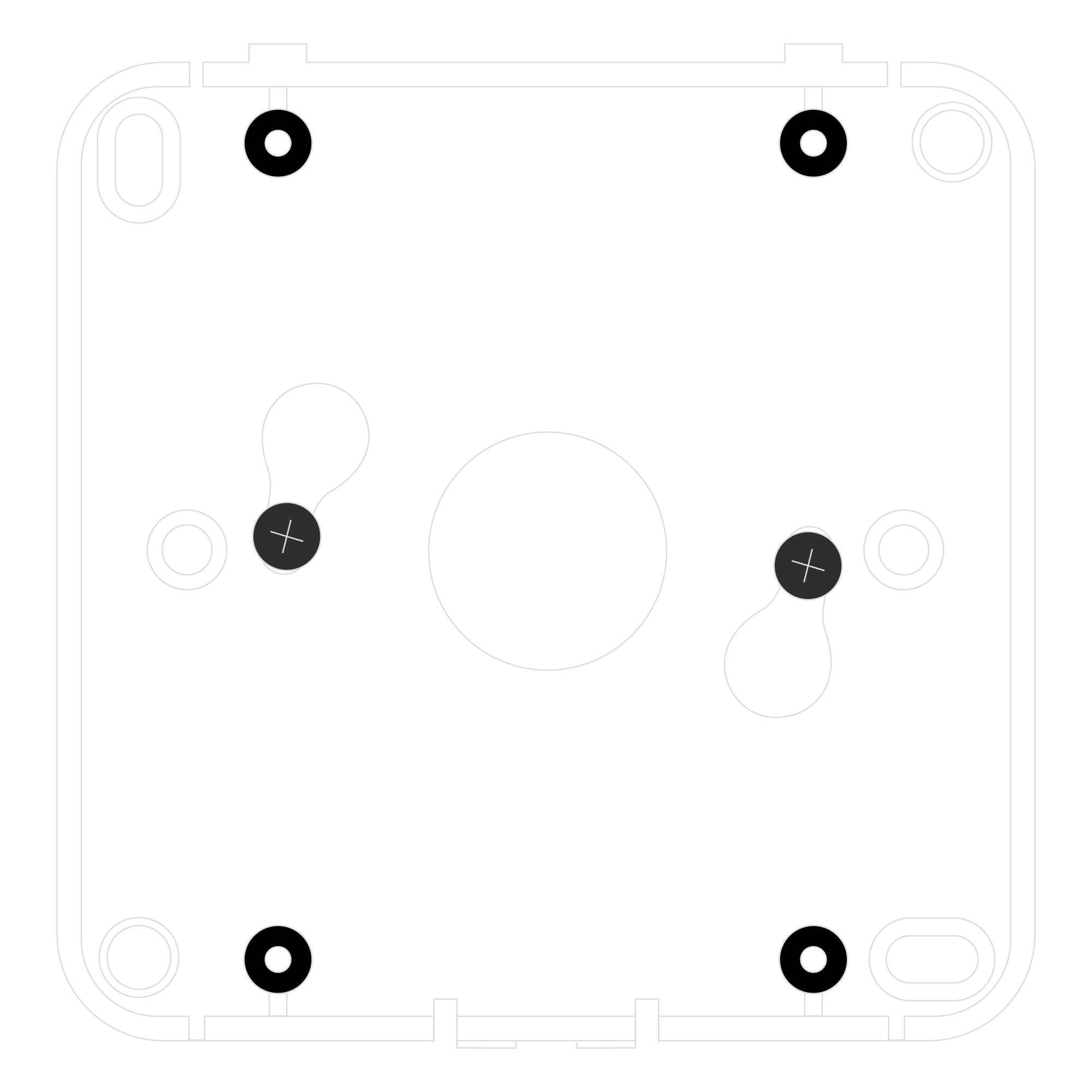
Figure 15. Mounting the device using two screws after a clockwise turn
- A. Install the bottom part of the enclosure and mount four screws in each corner to the wall.
Remember to route the supply cable through the centre of the bottom enclosure before mounting it to the ceiling or a wall.
- Place the upper part of the device enclosure on the bottom part mounted on a wall.
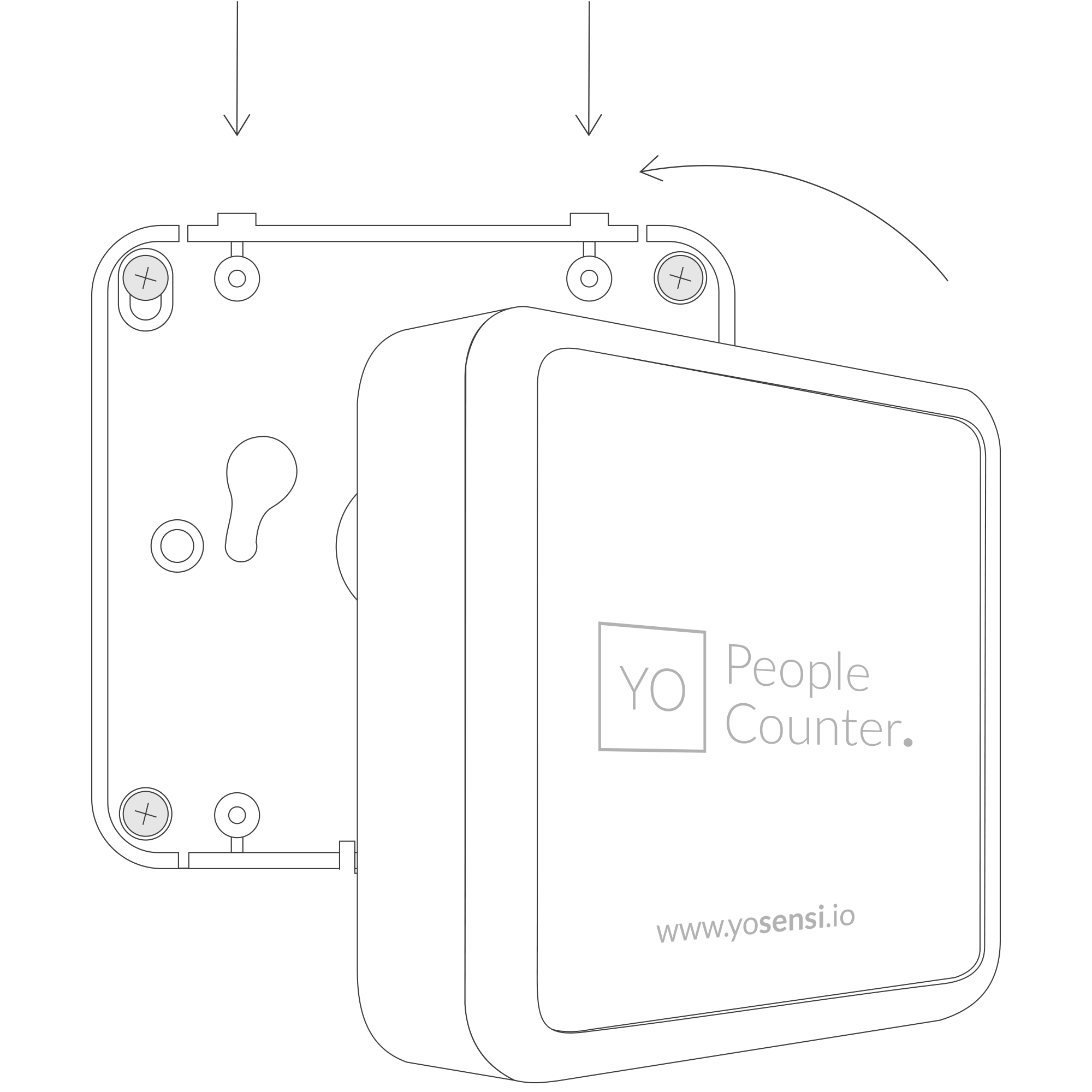
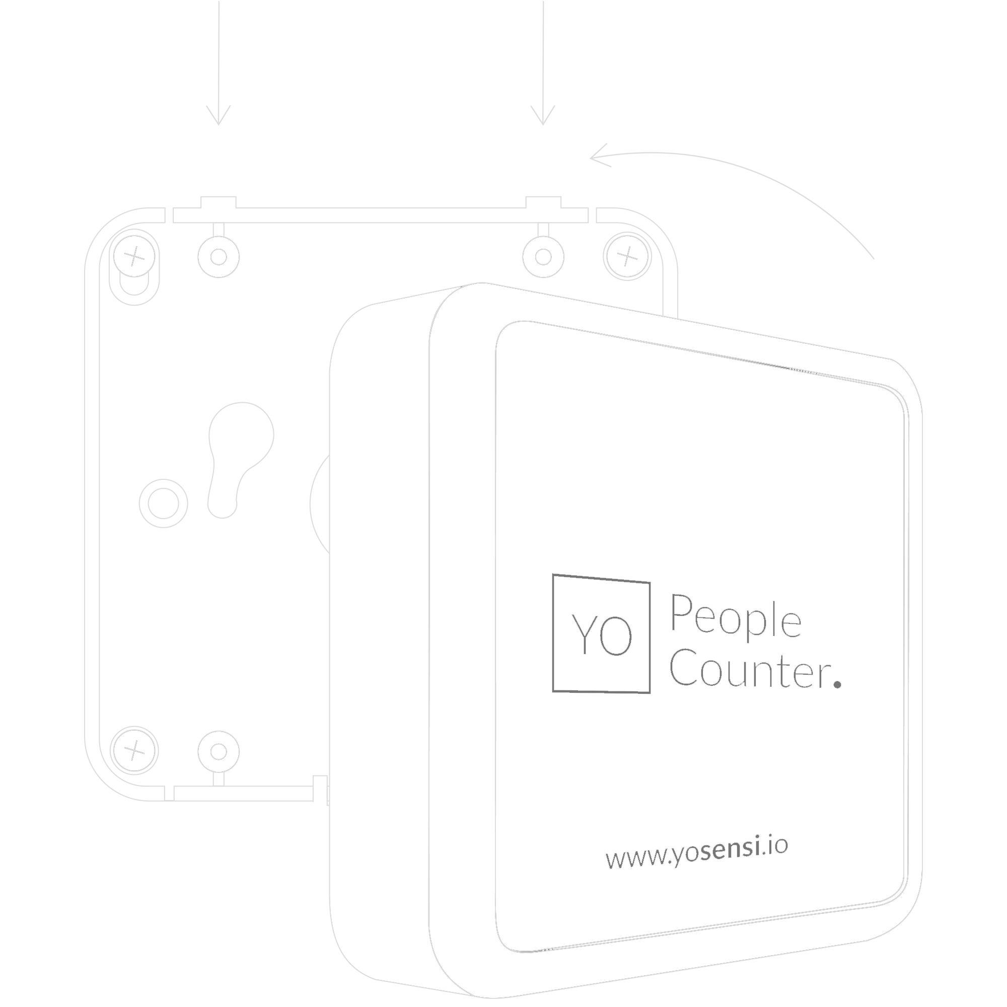
Figure 16. Placing the top of the enclosure on the mounting bracket
Configuration
Configurable Parameters
A few parameters must be set before sending data to the gateway. The default firmware is configured in OTAA mode with predefined deveui, appkey (OTAA) and appskey, nwkskey (ABP).
Configuration of the device is stored in a JSON file divided into the following sections:
- info (generic, read only): information about the device,
- lorawan (generic): configuration data for LoRaWAN connection,
- ble (generic): Bluetooth settings,
- device (dynamic): individual configuration for a specific device (this section’s structure differs for each device),
- detection area (dynamic): individual conguration for the YO People Counter that detects counts by various parameters. Depending on the application of the sensor in this section, you can configure its features.
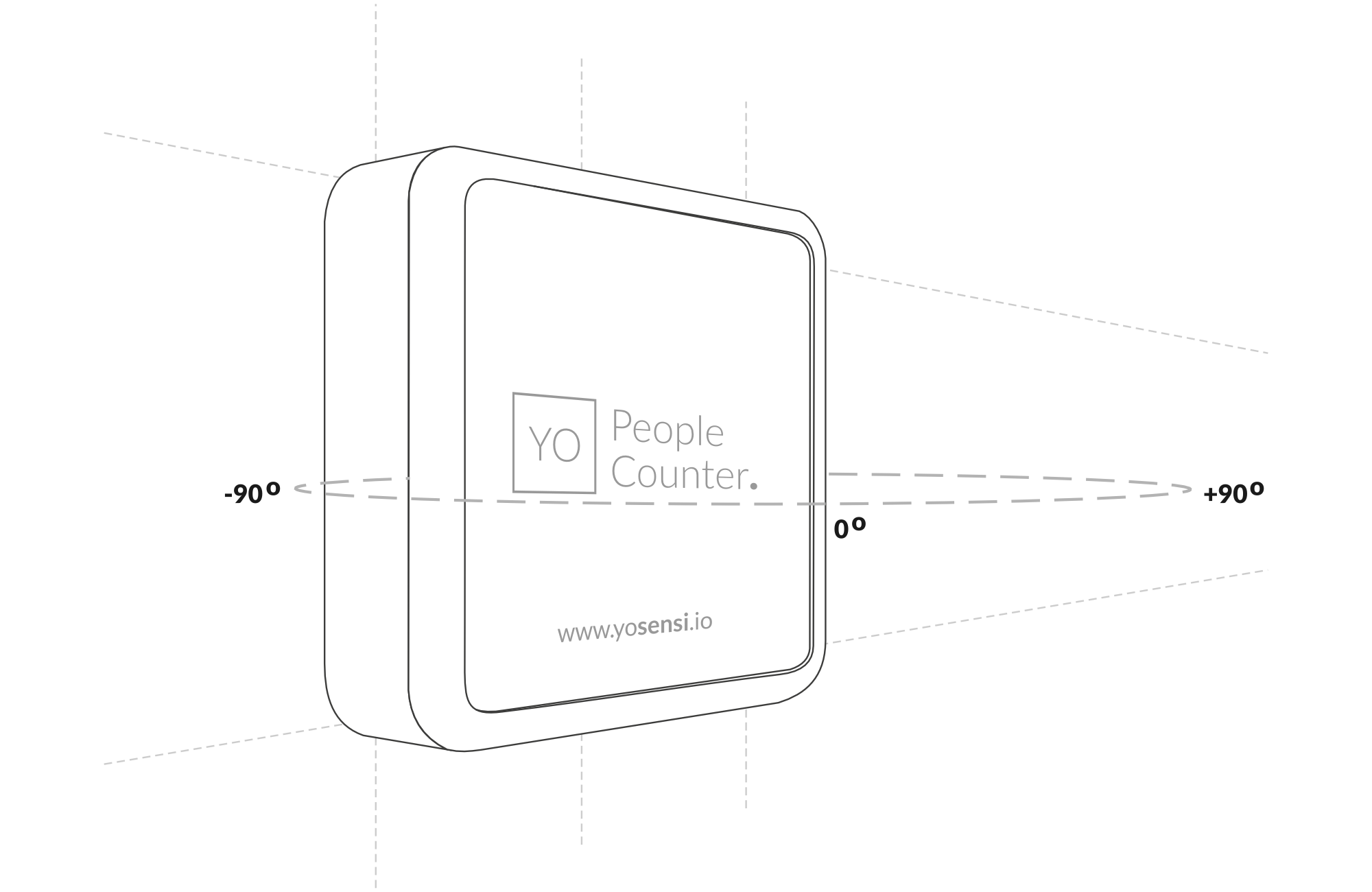
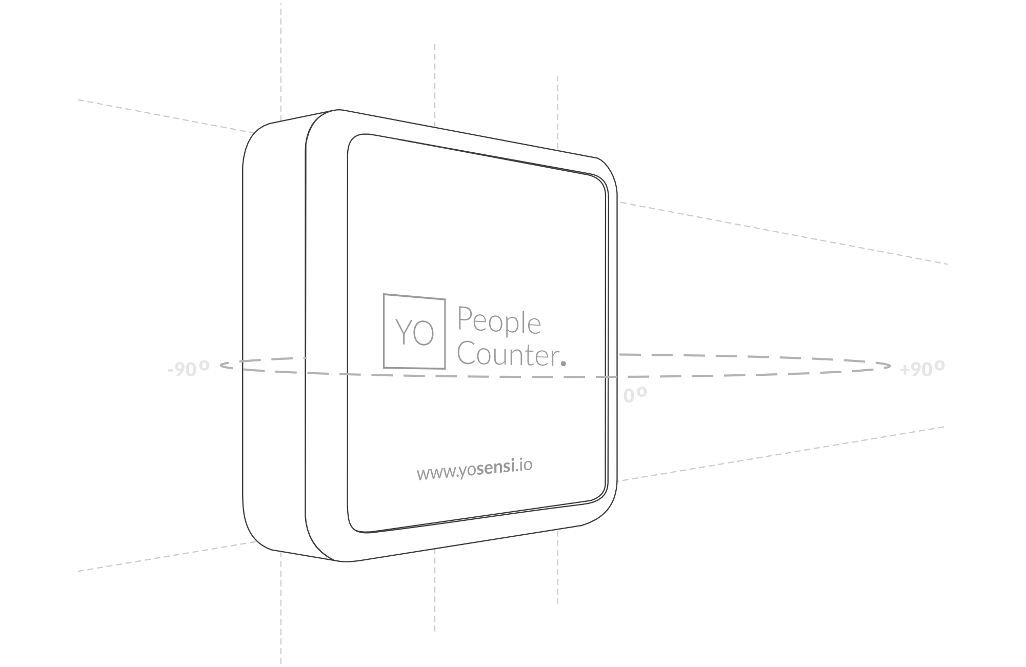
Figure 17. Detection Area
Sample configuration file for the YO People Counter device.
{
	"info": {
		"devmodel": "LNTP",
		"fwver": "3.6.3",
		"loraradio": "SX1261",
		"lorawanver": "1.0.2",
		"loraregion": "EU868",
		"blemacaddr": "0123456789ab"
	},
	"lorawan": {
		"subband": 1,
		"nwktype": "public",
		"acttype": "otaa",
		"otaa": {
			"deveui": "0123456789abcdef",
			"appeui": "fedcba9876543210",
			"appkey": "000102030405060708090a0b0c0d0e0f",
			"trials": 3
		},
		"abp": {
			"devaddr": "01234567",
			"nwkskey": "0123456789abcdef0123456789abcdef",
			"appskey": "000102030405060708090a0b0c0d0e0f"
	}
	},
	"ble": {
		"power": 0,
		"interval": 1600
	},
	"device": {
		"measinterval": 3600,
		"clearsumtime": 0
	},
	"detectionarea": {
		"holdtime": 1,
		"speedmax": 100,
		"speedmin": 0,
		"direction": "approach",
		"radarfreq": "low",
		"speedrange": 25,
		"distancemax": 50,
		"distancemin": 0,
		"sensitivity": 10,
		"trackfilter": "standard",
		"beamanglemax": 45,
		"beamanglemin": -45,
		"distancerange": 10,
		"speedthreshold": 50,
		"defaultsettings": "no",
		"distancethreshold": 10,
		"beamanglethreshold": 0
  	}
}
OTAA & ABP
| OTAA | ABP |
|---|---|
| Device EUI | Device Address |
| Application EUI | Network Session Key |
| Application Key | Application Session Key |
| Number of Trials |
Generic Parameters
Click here to see the generic parameters for Yosensi devices.
Parameters
Device Parameters
| Name | Description | Possible Values | Default Value | Read/Write |
|---|---|---|---|---|
| measinterval | Measuring and sending interval LoRa [s] | 601-999999 | 1800 | R/W |
| clearsumtime | Clearing the sum of people counters detection. Setting value to 0 equals to disable refreshing counters | 0-1440 [min] | 120 [min] | R/W |
| ||||
Detection Area Parameters
| Name | Description | Possible Values | Default Value | Read/Write |
|---|---|---|---|---|
| radarfreq | Frequency channel of the radar sensor | Low, middle, high | low | R/W |
| holdtime | Time between measurements. It is counted after the radar loses the object from its field of view | 1-7200 [s] | 1 | R/W |
| sensitivity | The sensitivity of the device sensor in [dB]. The highest is 10; 60 is the lowest | 10-60 [dB] | 30 | R/W |
| beamanglemin | The minimum beam angle of the sensor, describing the field of view of the device | -90° ÷ 90° | -30 | R/W |
| beamanglemax | The maximum beam angle of the sensor, describing the field of view of the device | -90° ÷ 90° | 30 | R/W |
| beamanglethreshold | The beam angle threshold for object detection approaching or moving away | -90° ÷ 90° | 0 | R/W |
| distancerange | Setting maximum distance range of the sensor | 5m, 10m, 30m, 100m | 10 | R/W |
| distancemin | Minimum distance detection field based on the percentage of distancerange | 0-100[%] | 0 | R/W |
| distancemax | Maximum distance detection field based on the percentage of distancerange | 0-100[%] | 50 | R/W |
| distancethreshold | Distance in percentage of distancerange that determines object detection below/above a given value | 0-100[%] | 10 | R/W |
| speedrange | Sets the speed range of measurement | 12.5km/h, 25km/h, 50km/h, 100km/h | 25 | R/W |
| speedmin | Minimum speed in percentage of speedrange | 0-100[%] | 0 | R/W |
| speedmax | Maximum speed in percentage of speedrange | 0-100[%] | 100 | R/W |
| speedthreshold | Speed in percentage of speedrange determining object detection below/above a given value | 0-100[%] | 50 | R/W |
| direction | Direction of objects approaching or moving away from the sensor | Receding, approaching, both | approach | R/W |
| tracklter | Determines target filtering: standard (default), fast detection, or high interference immunity | Standard, fast, long | standard | R/W |
| defaultsettings | Sets default values for all detection area parameters | no, yes | no | R/W |
Parameters description
- nwktype: used for setting the device in public or private network type.
- acttype: used for setting the device in ABP or OTAA mode.
- deveui, … , appskey: predefined addresses and keys, these parameters are generated using multiple IDs specific to the particular MCU and are unique for each device. They can be changed if needed.
- interval: determines the interval of sending broadcast packets, used to connect to every BLE receiver around the device.
- subband: used for setting the communication frequency sub-band in LoRaWAN.
- measinterval: measurement interval [s] between sending LoRa packets.
- clearsumtime: If, after a given time, there is no movement detected, the device clears its counters.
- radarfreq: Frequency channel of the radar sensor mounted on the device.
- holdtime: Parameter that keeps the information about tracking an object or person passing by from one side to another. It counts the time between additional measurements after the object leaves the radar field of view.
- sensitivity: Sensitivity of the radar to detect people passing near the device, measured in dB; 10 is the highest, and 60 is the lowest.
- beamanglemin: Describes the field of view of the sensor. The minimum beam angle detects a person passing the device's field of view. Negative or positive values define a wider or shorter target detection field.
- beamanglemax: Describes the field of view of the sensor. The maximum beam angle detects a person passing the device's field of view. Negative or positive values define a wider or shorter target detection field.
- beamanglethreshold: Describes the field of view of the sensor. A parameter in an angle checks when a person or object moves near the sensor from one side to another. A default value of zero means the person went from the left or right side, informing the sensor about approaching or moving away.
- trackfilter: There are three types of track filters:
- Standard: Tracks various targets, such as cars or people.
- Fast: Enables faster detection of targets but reduces immunity to reflections and interference.
- Long: Provides high immunity against interference and better prediction of temporarily lost targets.
- defaultsettings: Parameter that helps the user return to default settings in case of configuration errors. Set the value to
trueto reset and upload to the device. - distancerange: Maximum distance range for measurements.
- distancemin: Minimum distance in percentage value of the
distancerangeparameter between the device and a person. - distancemax: Maximum distance in percentage value of the
distancerangeparameter between the device and a person. - distancethreshold: Detects objects entering the sensor's field of view. If a target exceeds the threshold given as a percentage of the maximum distance, it provides information about the target approaching or moving away.
- speedrange: Speed range for detecting a walking person or object approaching the sensor's field of view.
- speedmin: Minimum speed in percentage value of the
speedrangeparameter. - speedmax: Maximum speed in percentage value of the
speedrangeparameter. - speedthreshold: A percentage of the
speedmaxparameter. After detecting a moving object in the sensor's field of view, it calculates how fast the target is moving. Tangential movement requires speed adjustment based on the angle relative to the sensor. - direction: Parameter that describes whether an object or person is approaching the sensor, receding from it, or both.
Downlink message
You can remotely adjust certain parameters by sending a downlink message through our platform. Simply navigate to the "COMMANDS" section for the selected device.
Update Measurement Interval
It is possible to change the measurement interval (measinterval) by using downlink. Information about changing the parameter will be sent from the server via the gateway.
Example of Downlink Message:
- Prefix:
0x03 - Measurement Index:
0x00 - Data (up to 4 bytes in hex):
0x0258
Sample Downlink: 0x03000258 - Sets a measurement interval of 600 seconds (10 minutes).
Update Clear Sum Time
It is possible to change the Clear sum time (clearsumtime) by using downlink.
Example of Downlink Message:
- Prefix:
0x03 - Measurement Index:
0x01 - Data (up to 4 bytes in hex):
0x00c8
Sample Downlink: 0x030100c8 - Sets the clear sum time to 200.
Update Clear All Counters
It is possible to change the Clear all counters by using downlink.
Example of Downlink Message:
- Prefix:
0x03 - Measurement Index:
0x02 - Data (up to 4 bytes in hex):
0x01
Sample Downlink: 0x030201 - Sets the clear all counter to 1.
Click here to see how to connect a node using the Yosensi Management Platform.
See how to configure a node in Yosensi Management Platform
Check how to adopt and configure a node via the Yosensi App.
Take a look at the list of frequency plans used in Yosensi.
This datasheet describes the payload protocol developed by Yosensi for communicating with our devices.
Payload Decoder
If you want to connect to your own server, it is necessary to decode the specific payload for each device. To accomplish this, a payload decoder is required, which can be downloaded using the following link: Payload decoder. You can also use our integrated Payload Decoder here. Extended documentation of the protocol can be found in the Payload description on our website.
Compliance Statements
To view or download the Declaration of Conformity for YO People Counter go here