YO Thermostat
Overview
Description
The YO Thermostat is an advanced device designed to monitor and regulate indoor conditions with precision. It measures temperature, humidity, illuminance, and optional CO2 levels while providing occupancy tracking through an infrared presence sensor with a built-in counter. Equipped with a PID controller, the thermostat ensures consistent temperature regulation by comparing room temperature to a setpoint and fine-tuning its state accordingly. The controller’s output is transmitted via LoRaWAN, enabling seamless integration with actuators like the YO Relay Switch for controlling HVAC systems, heaters, or other devices. Ideal for maintaining optimal indoor environments, the YO Thermostat enhances occupant comfort, productivity, and well-being. Its wireless and battery-operated design ensures easy installation and flexibility in various applications.
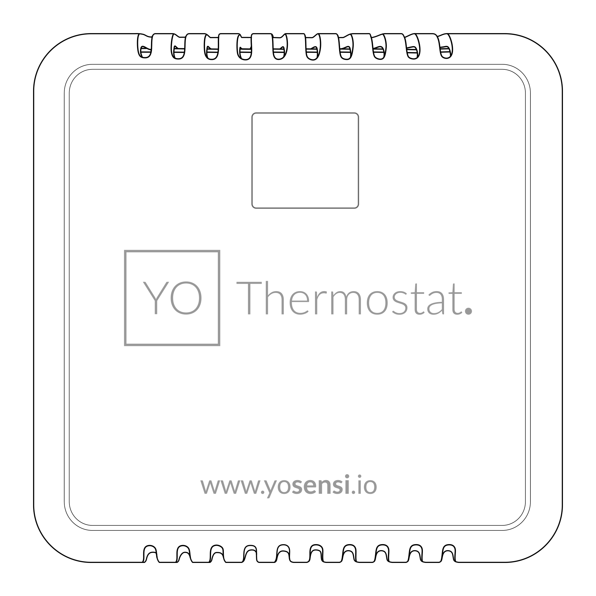
Figure 1. Device top view
Device sticker placed on the right side of the device enclosure contains information about model, version, LoRaWAN region and 3 parameters important in case of device identification and configuration:
- DEV EUI: 64-bit unique device identifier in a LoRaWAN network,
- DEV ADDR: address required to connect via ABP activation type to LoRaWAN,
- BLE MAC: Bluetooth physical address.
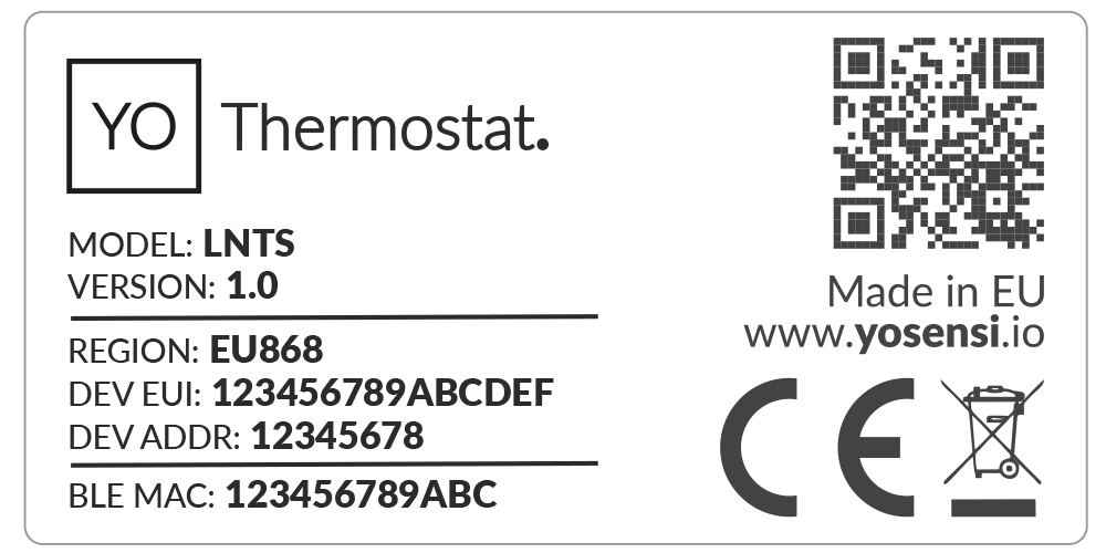
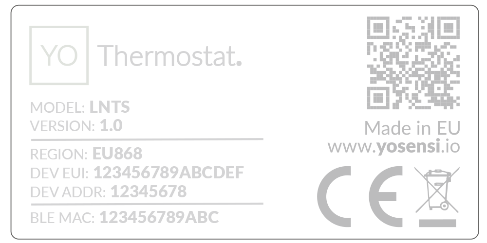
Figure 2. Device sticker
Features
- LoRaWAN Technology: Available in multiple versions with LoRa radio configured for various regions and ISM frequency bands (e.g., EU868, US915, AU915), it is compatible with both private and public LoRaWAN networks and supports connections via ABP (Activation by Personalization) or OTAA (Over-The-Air Activation).
- Bluetooth Low Energy (BLE): Enables easy configuration through a user-friendly JSON data exchange format, supports firmware updates via OTA (Over-the-Air), and boasts very low energy consumption.
- Battery-Powered: 3x AA lithium batteries featuring very low self-discharge, ensuring long-term operation without the need for an external power supply.
- Temperature and Relative Humidity: Measures temperature and relative humidity within the device enclosure, providing valuable insights into the surrounding environment.
- Illuminance: Equipped with a sensor to measure light intensity, ensuring the room has adequate lighting levels.
- CO2 (optional): Tracks CO2 levels to ensure a healthy indoor environment, helping to prevent reduced concentration and increased heart rate caused by elevated levels.
- Infrared occupancy: Features an infrared motion sensor with a built-in occupancy counter to track the number of people entering or exiting a room.
- Thermostat Output Signal Status: PID-controlled on-off output signal ensures precise and stable temperature regulation by continuously adjusting to ambient conditions.
- Yosensi Management Platform: Provides a web tool for device configuration, firmware updates, and infrastructure management. Enables comprehensive monitoring of transmitted data and easy device management.
- Yosensi Mobile App: Effortlessly manage devices with features to register new ones, configure settings, perform firmware updates, view/send logs, and test LoRaWAN connectivity. Learn more in our detailed Yosensi App blog post.
Specifications
Physical
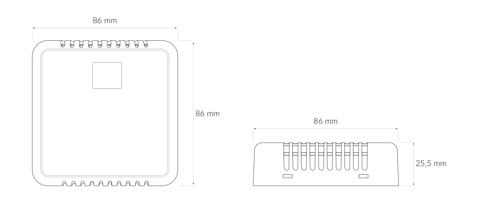
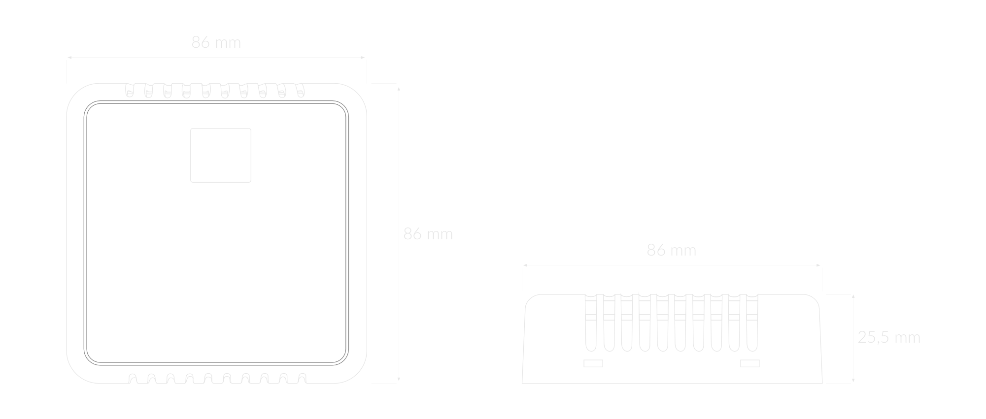
Figure 3. Dimensions of the device
Device
| Attribute | Description |
|---|---|
| Dimensions | Height: 25.5 mm Width: 86 mm Depth: 86 mm |
| Colour | White |
| Mounting method | Horizontal Vertical (can be screwed to the wall) |
| Enclosure material | ABS |
| Level of protection | IP40, UL94-V0 |
| Weight | 82.5 g (without batteries) |
Operating Conditions
| Attribute | Description |
|---|---|
| Temperature | 0°C to 70°C |
| Humidity | 0 to 90% |
| Placement | Indoor use |
| Power supply | 3 x LR6 (AA) battery (3 x 1.5 V) |
| Power consumption | Maximum: 120 mA DC (4.5 V DC) |
Measured Values
| Parameter | Measurement range | Accuracy |
|---|---|---|
| Temperature (internal) | -40°C to 125°C | ±0.2°C (5°C to 60°C) |
| Relative humidity (internal) | 0% to 100% | ±2% (20% to 80%) |
| CO2 (optional) | 0 to 40.000 ppm | ±(40 ppm+5%) from 400 ppm to 5000 ppm |
| Recommended working conditions: -10°to 60 °C | ||
| Illuminance | 0 to 120 klx | ±10% at 25°C |
| Infrared presence sensor | 0 to 4.5 metres, 80° field of view |
Controls and Indicators
LED Status Indicator
YO Thermostat communicates its current behaviour to the user by RGBW LED placed on the bottom.
Diode statuses interpretation
| Behavior | Colour | Status |
|---|---|---|
| Single flash | Green | General: device is working correctly (power and memory). |
| Single flash | Red | General: device is working incorrectly (power and memory). LoRaWAN communication: failed to receive an acknowledgement from LoRaWAN Server within specified timeout. |
| Single flash | White | LoRaWAN communication: LoRaWAN frame sent / confirmation from LoRaWAN Server after receiving the frame. |
| Slow flashing | Blue | BLE communication: connection to the device via BLE (configuration). |
| Rapid flashing | Blue | LoRaWAN communication: connecting to LoRaWAN network. |
Buttons
The YO Thermostat has a button for resetting the device. Figure 4 shows its placement. To reboot the device, press the reset button for a moment.
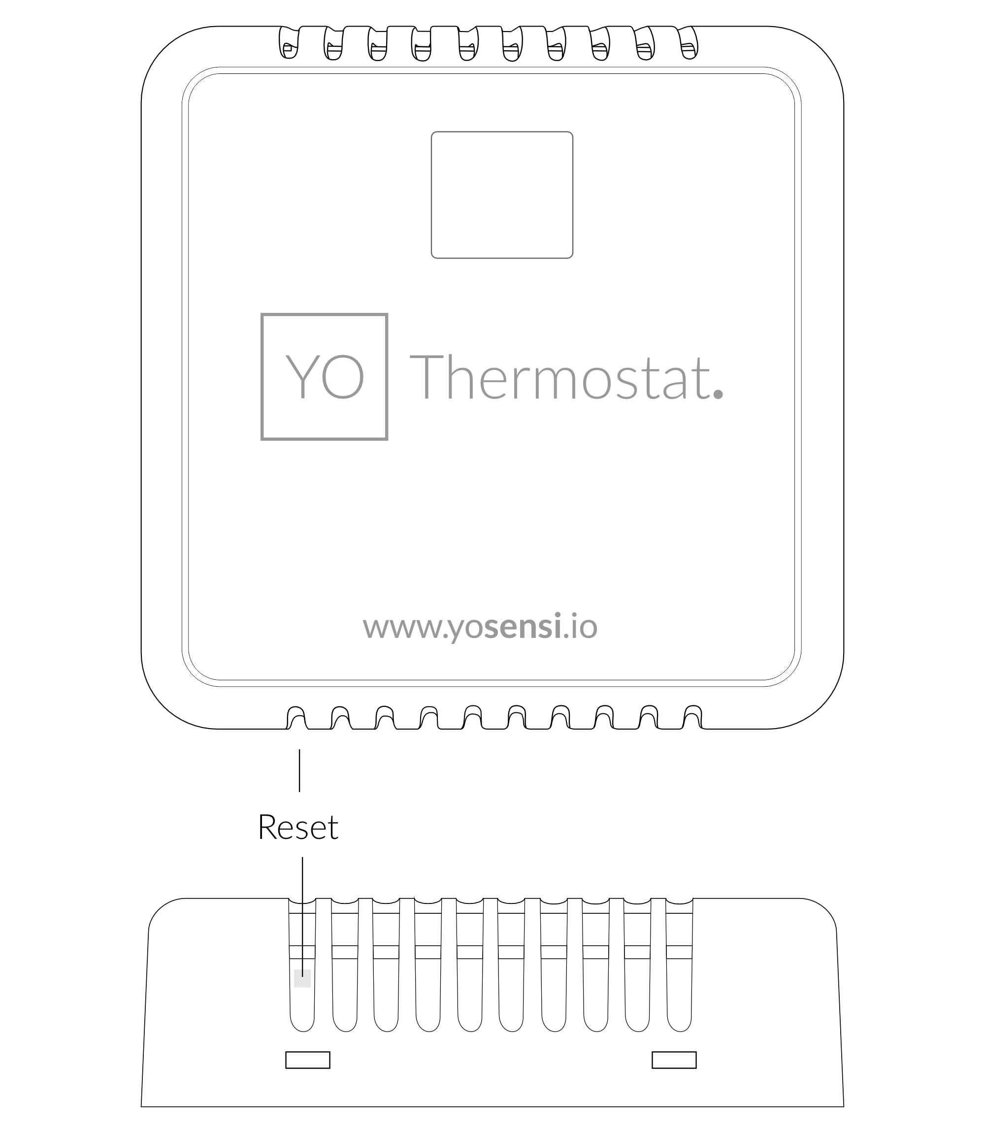
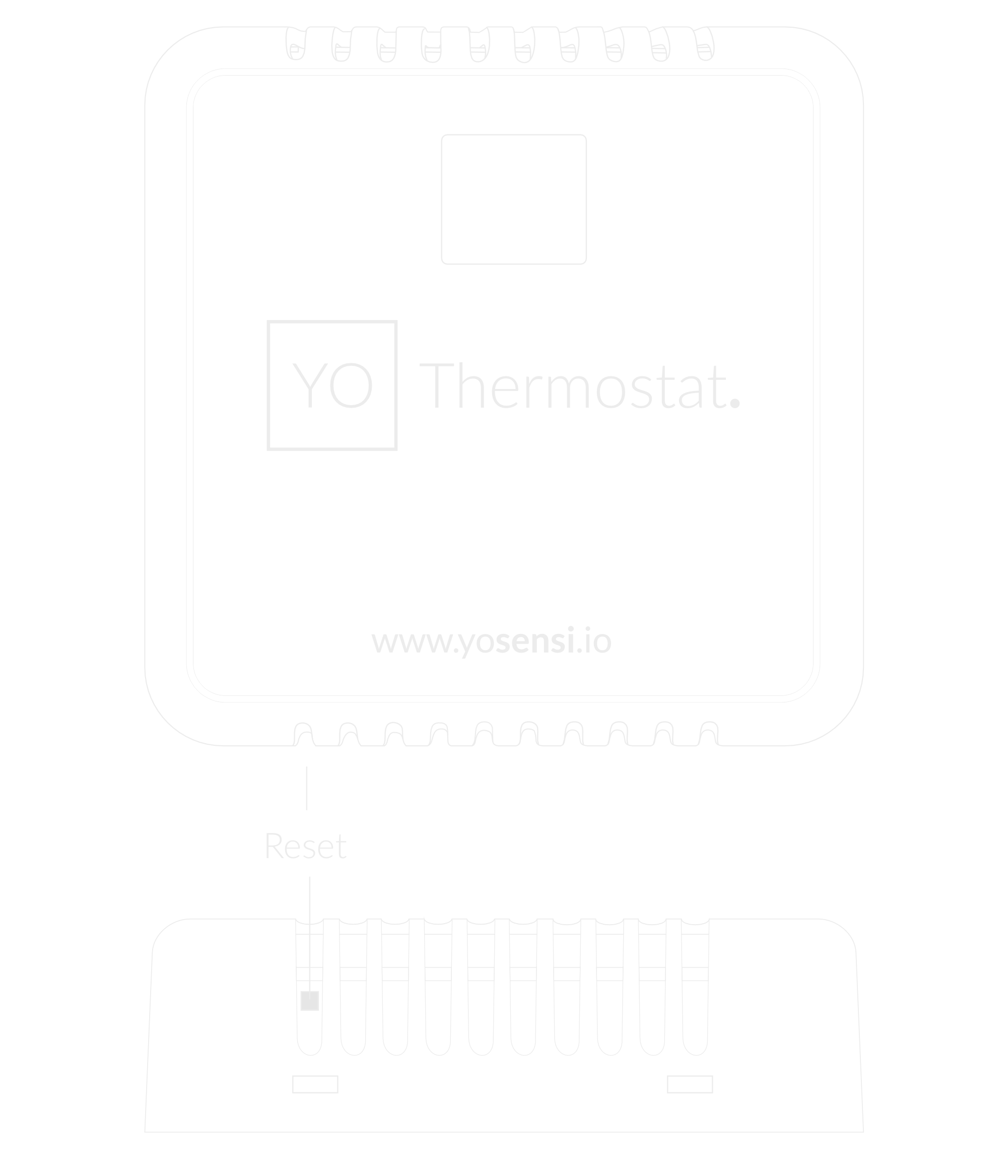
Figure 4. Reset button
Installation
Package Contents
- Device (without batteries).
- Warranty card.
Safety Precautions
Go to the Safety Precautions section to see important information on handling, disposal and maintenance.
Installation Guide
- To open the enclosure, pry off the lower part.
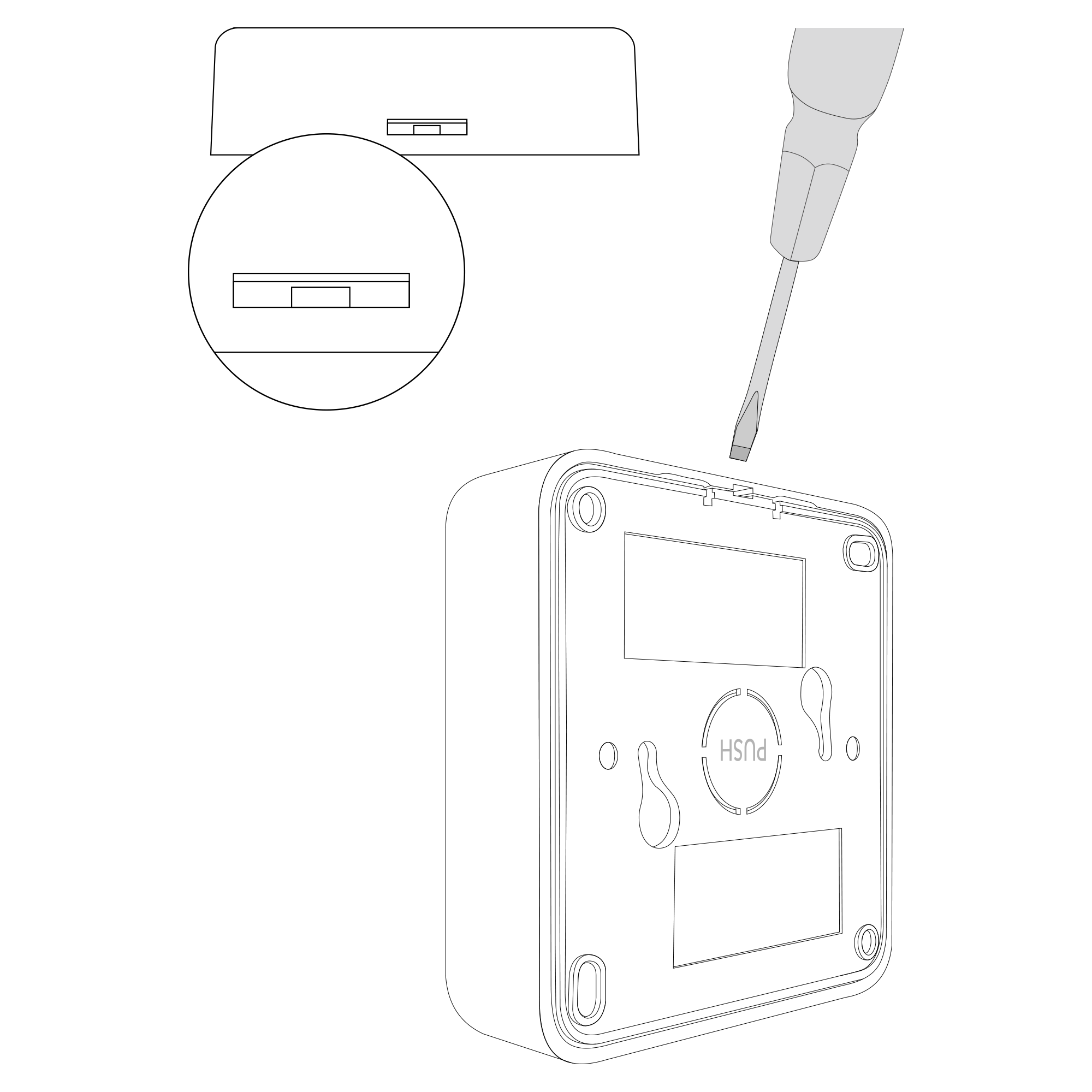
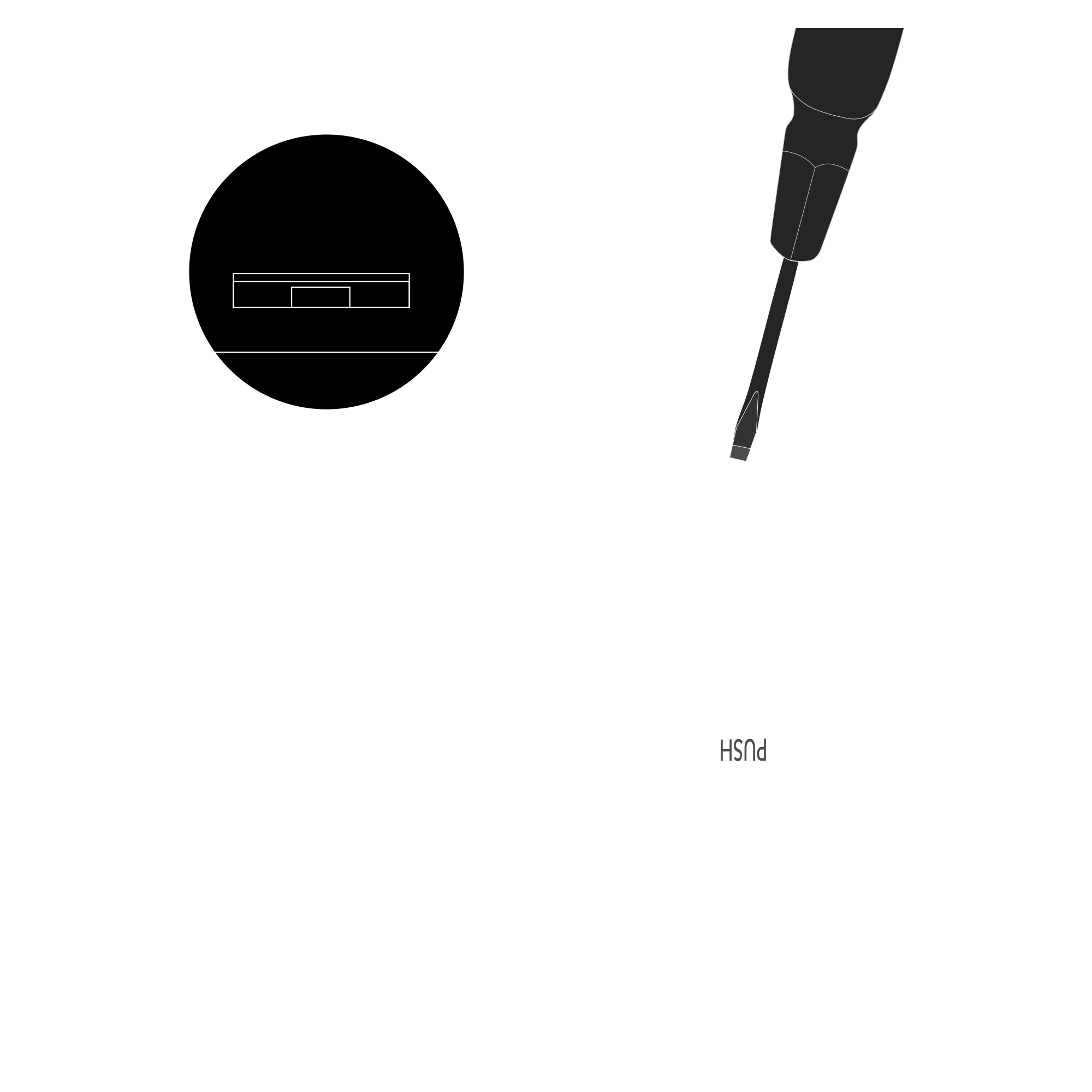
Figure 5. Device opening instructions
- Place three LR6 batteries in the device according to the polarity indicated on the battery holder.
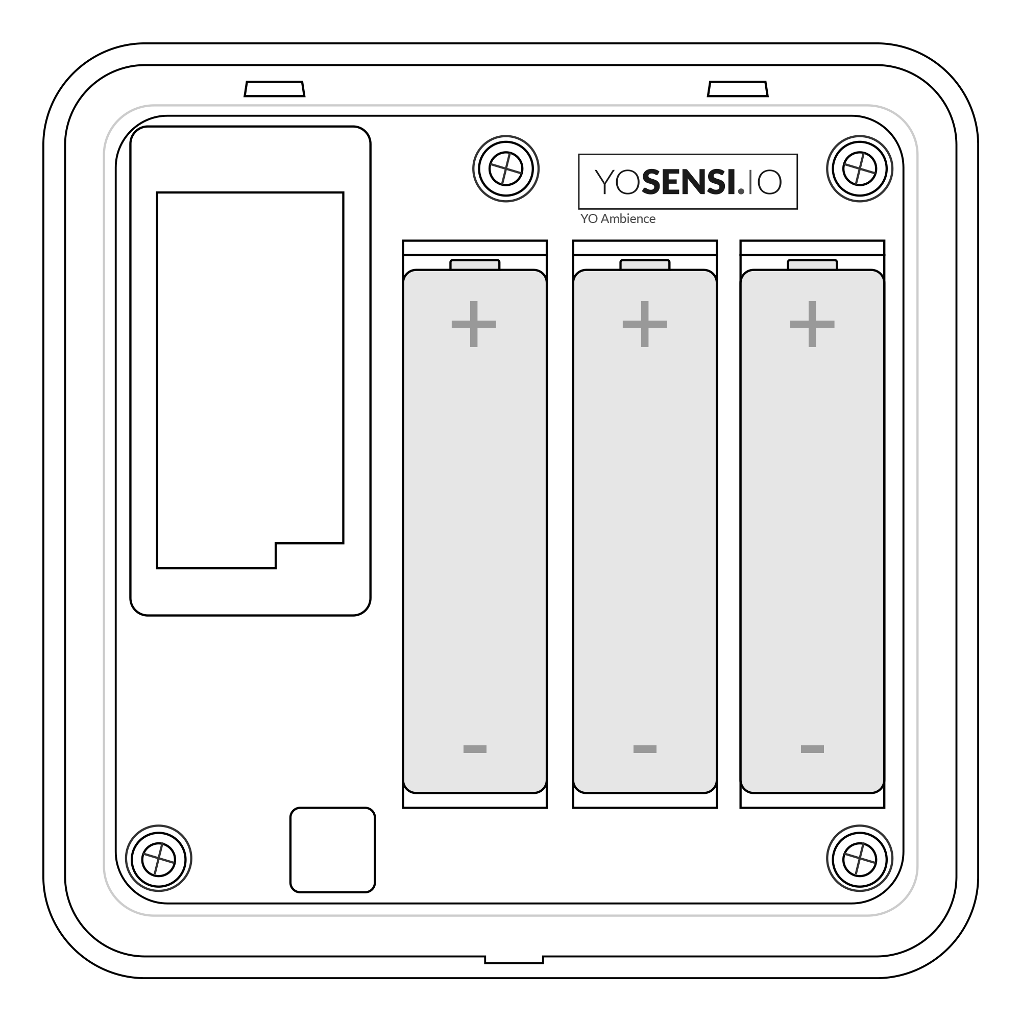
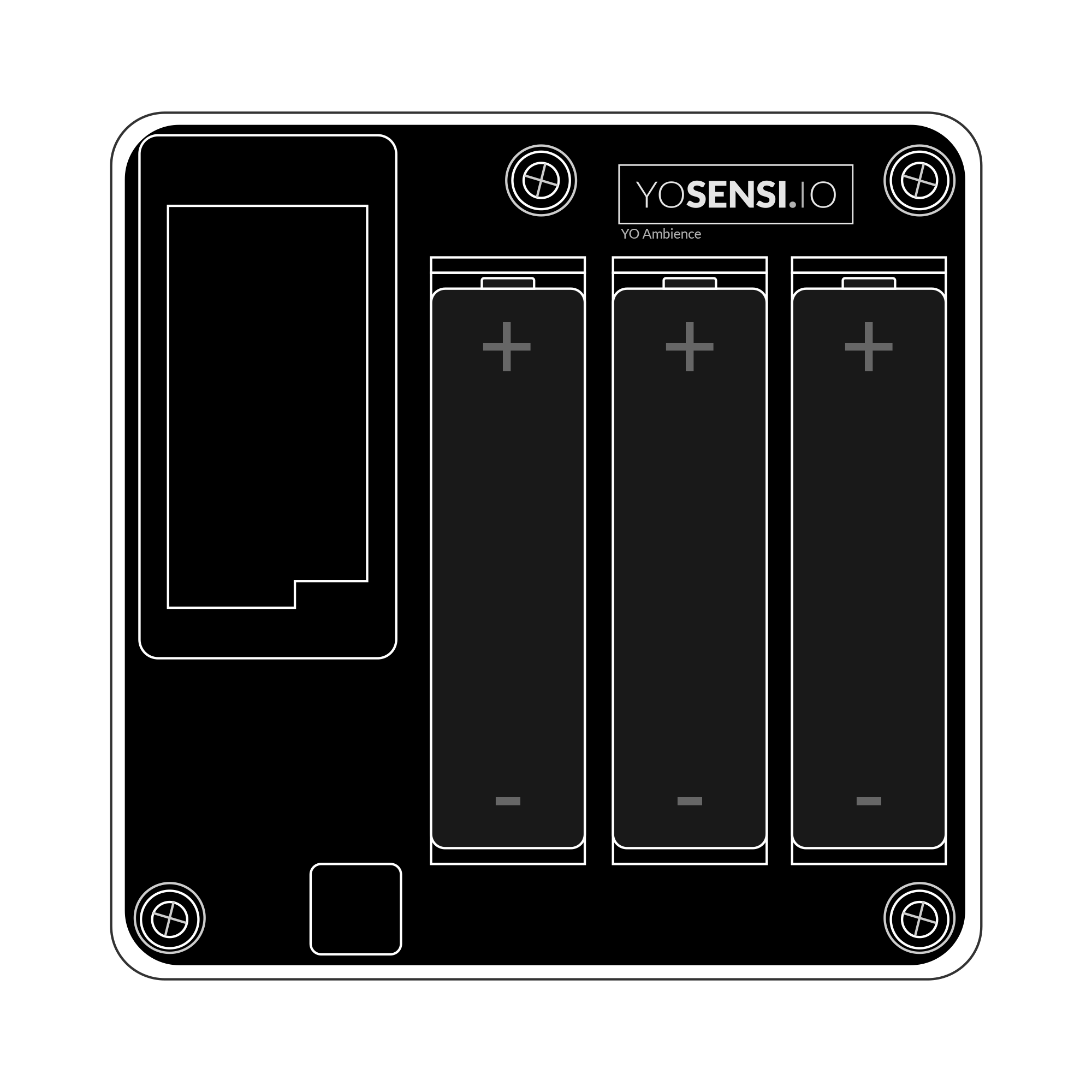
Figure 6. Device with placed batteries
-
There are two ways to mount the device on a wall.
- A. Install the bottom part of the enclosure and mount four screws in each corner to the wall.
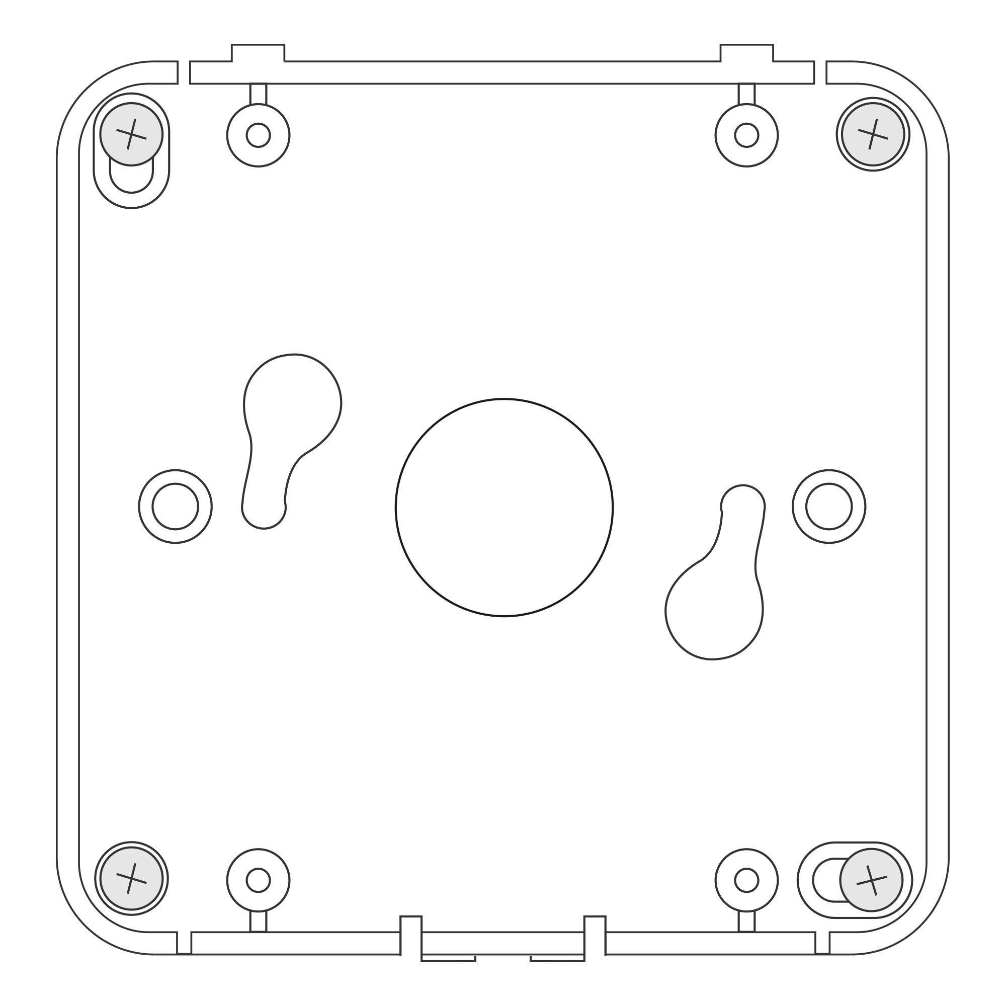
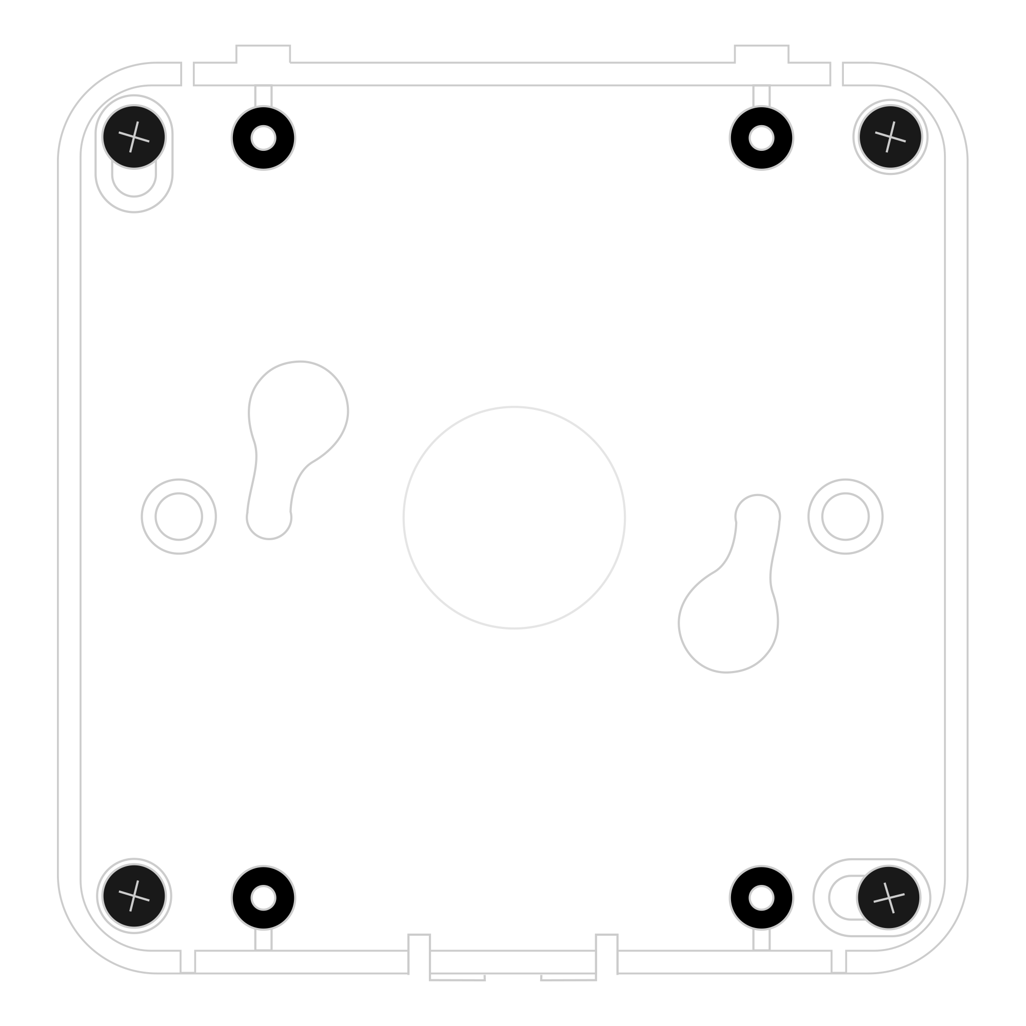
Figure 7. Mounting the device using four screws
- B. Fit two mounting screws into the centre of the bottom case. Then, angle the bottom of the enclosure and turn it clockwise.
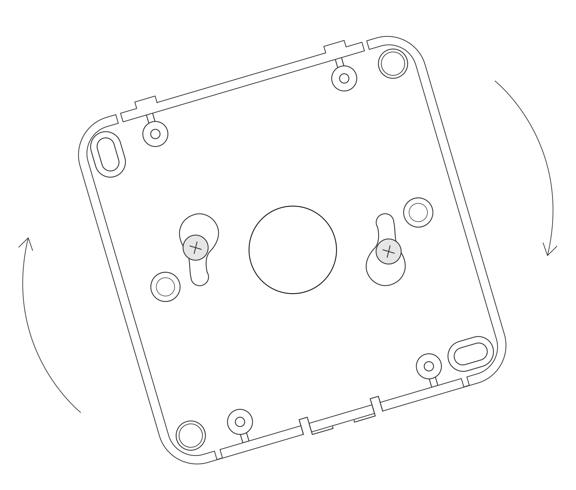

Figure 8. Mounting the device using two screws at an angle
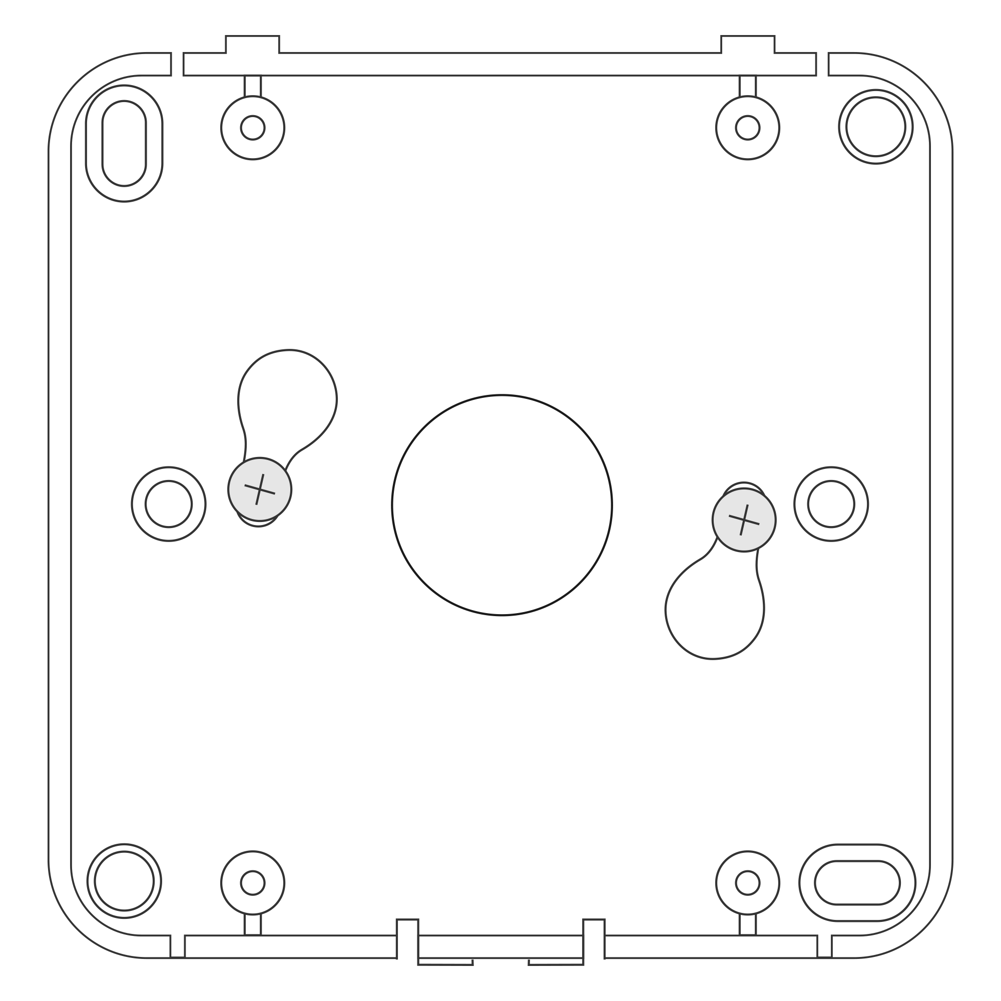
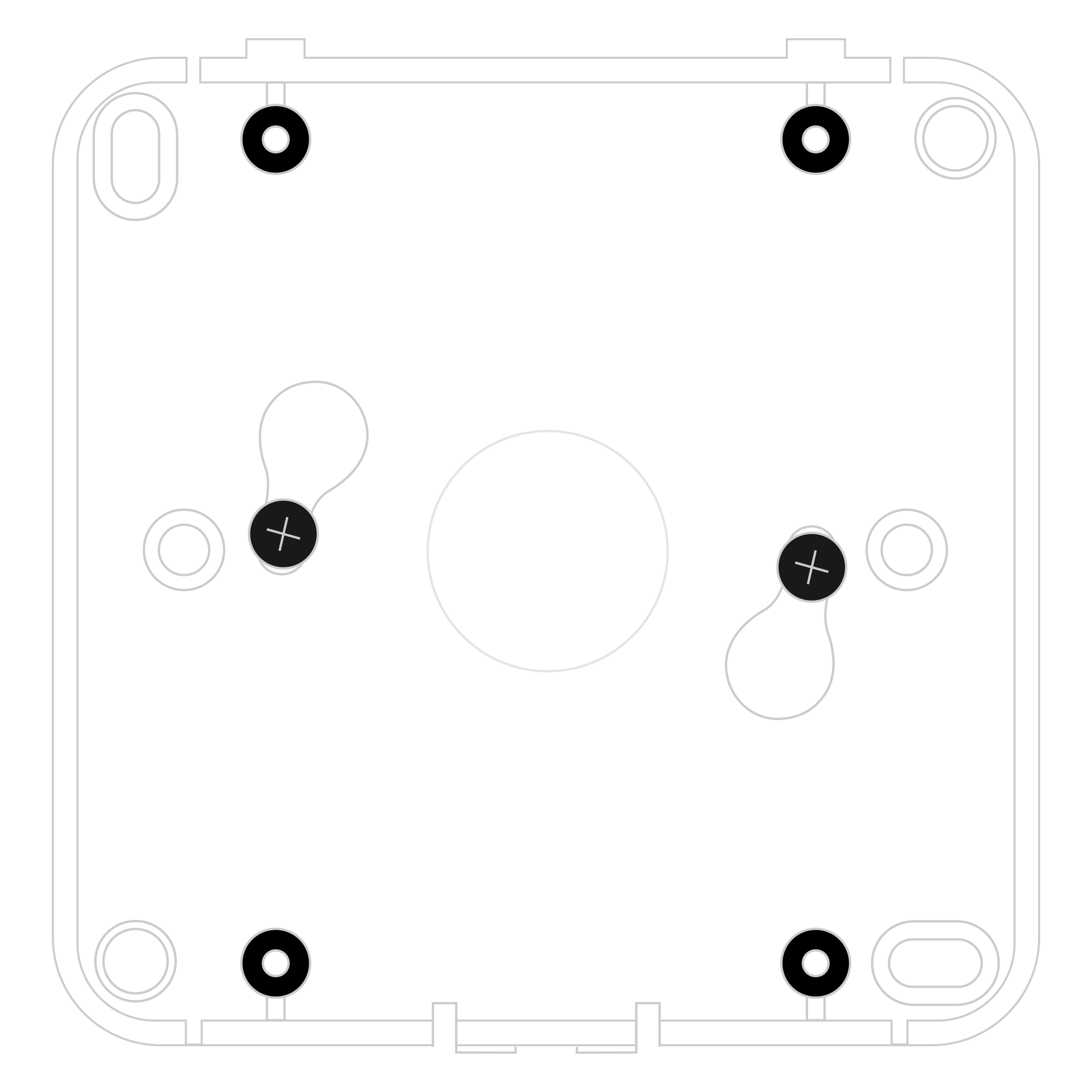
Figure 9. Mounting the device using two screws after a clockwise turn
- A. Install the bottom part of the enclosure and mount four screws in each corner to the wall.
-
Place the upper part of the device enclosure on the bottom part mounted on a wall.
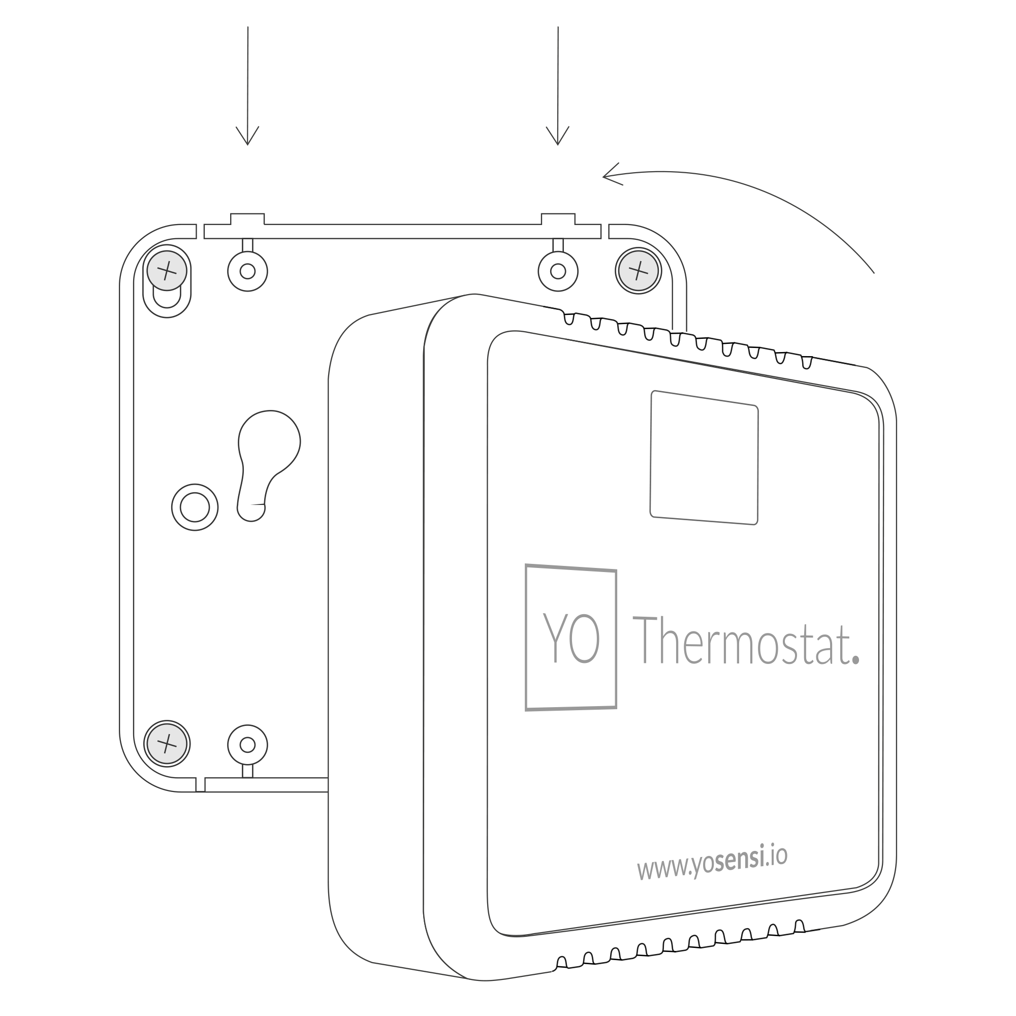
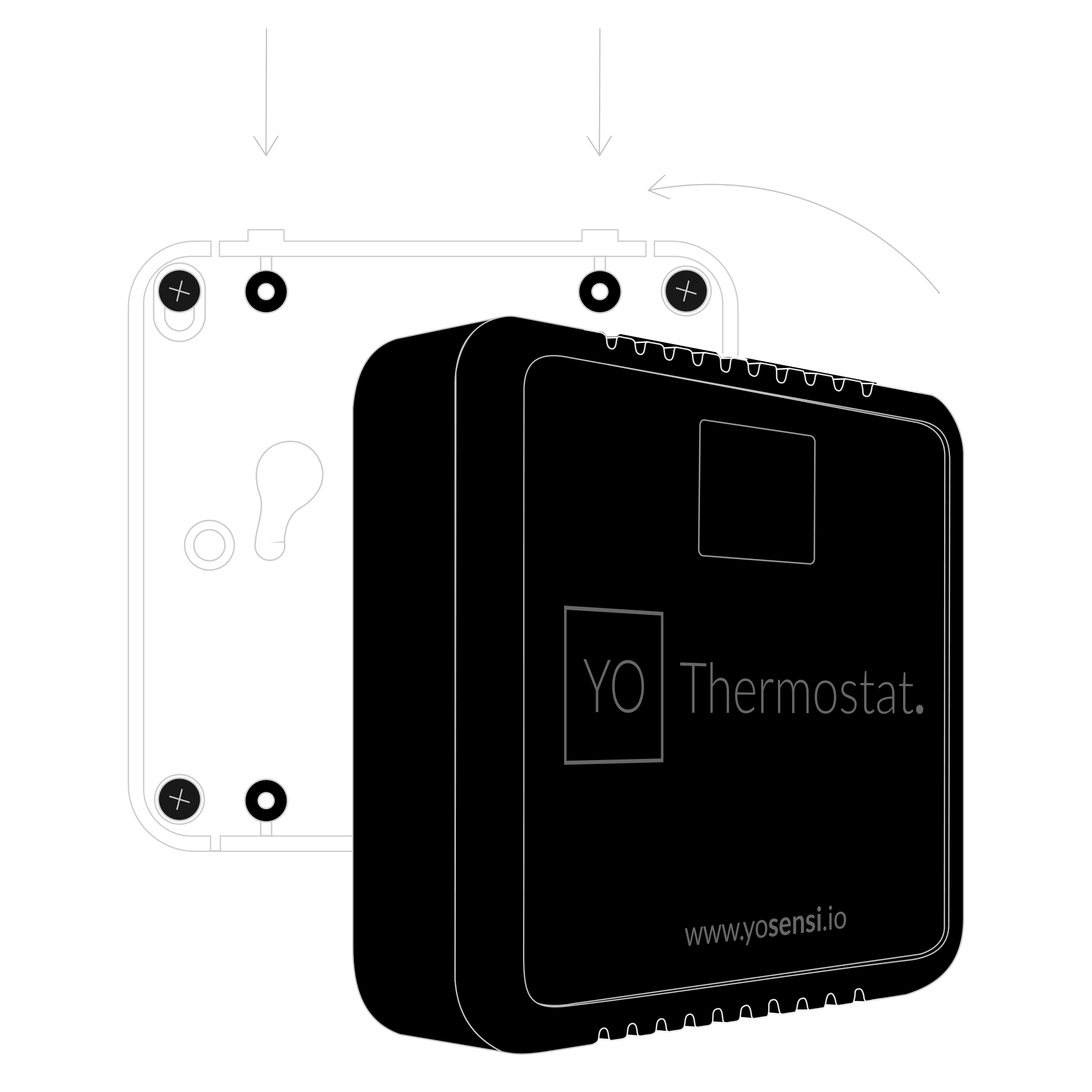
Figure 10. Placing device on the wall
Configuration
Configurable Parameters
A few parameters must be set before sending data to the gateway. The default firmware is configured in OTAA mode with predefined deveui, appkey (OTAA) and appskey, nwkskey (ABP).
Configuration of the device is stored in a JSON file divided into the following sections:
- info (generic, read only): information about the device,
- lorawan (generic): configuration data for LoRaWAN connection,
- ble (generic): Bluetooth settings,
- device (dynamic): individual configuration for a specific device (this section’s structure differs for each device),
Sample configuration file for the YO Thermostat device.
{
	"info": {
		"devmodel": "LNTS",
		"fwver": "1.0.0",
		"loraradio": "SX1261",
		"lorawanver": "1.0.2",
		"loraregion": "EU868",
		"blemacaddr": "0123456789ab"
	},
	"lorawan": {
		"subband": 1,
		"nwktype": "public",
		"acttype": "otaa",
		"otaa": {
			"deveui": "0123456789abcdef",
			"appeui": "fedcba9876543210",
			"appkey": "000102030405060708090a0b0c0d0e0f",
			"trials": 3
		},
		"abp": {
			"devaddr": "01234567",
			"nwkskey": "0123456789abcdef0123456789abcdef",
			"appskey": "000102030405060708090a0b0c0d0e0f"
	}
	},
	"ble": {
		"power": 0,
		"interval": 1600
	},
	"device": {
		"tempoffset": 0,
		"thermostat": {
			"regkd": 0.5,
			"regki": 2,
			"regkp": 5,
			"cycletime": 900,
			"economyoffset": -4,
			"standbyoffset": -2,
			"comfortsetpoint": 21,
			"computinginterval": 60,
			"frostprotsetpoint": 7,
			"oprmodeafterreset": 5
		},
		"co2calibval": 0,
		"measinterval": 3600,
		"illuminancecoeff": 1.6
	}
}
OTAA & ABP
| OTAA | ABP |
|---|---|
| Device EUI | Device Address |
| Application EUI | Network Session Key |
| Application Key | Application Session Key |
| Number of Trials |
Generic Parameters
Click here to see the generic parameters for Yosensi devices.
Parameters
Device Parameters
| Name | Description | Possible Values | Default Value | Read/Write |
|---|---|---|---|---|
| measinterval | Measuring and sending interval LoRa [s] | 601-999999 | 3600 | R/W |
| co2calibval | Calibration value of CO2 sensor [ppm] | 0-9999 | 0 | R/W |
| tempoffset | Temperature offset in [°C] | -20.0-20.0 | 0 | R/W |
| iluminancecoeff | Illuminance coefficient | 0.0-10.0 | 1.6 | R/W |
| comfortsetpoint | Comfort set point | 7.0-40.0 | 21.0 | R/W |
| standbyoffset | Standby offset | -0.1-(-8.0) | -2.0 | R/W |
| economyoffset | Economy offset | -0.1-(-10.0) | -4.0 | R/W |
| frostprotsetpoint | Frost protection set point | 7.0-40.0 | 7.0 | R/W |
| opermodeafterreset | Operating mode after reset | 0, 1, 2, 3, 4, 5 | 5 | R/W |
| cycletime | Cycle time [s] | 600-9999 | 900 | R/W |
| computinginterval | Computing interval | 1-300 | 60 | R/W |
| regkp | Regulator proportional gain | 1-8 | 5.0 | R/W |
| regki | Regulator integral gain | 0-6 | 2.0 | R/W |
| regkd | Regulator derivative gain | 0-4 | 0.5 | R/W |
| ||||
Parameters description
- nwktype: used for setting the device in public or private network type.
- acttype: used for setting the device in ABP or OTAA mode.
- deveui, … , appskey: predefined addresses and keys, these parameters are generated using multiple IDs specific to the particular MCU and are unique for each device. They can be changed if needed.
- interval: determines the interval of sending broadcast packets, used to connect to every BLE receiver around the device.
- subband: used for setting the communication frequency sub-band in LoRaWAN.
- measinterval: measurement interval [s] between sending LoRa packets.
- co2calibval: Calibration value of the CO2 sensor, providing high initial and long-term accuracy. Enables the sensor to restore optimal accuracy using a CO2 reference value, used if measurement stability deviates. A value of 0 disables calibration.
- tempoffset: Offset value applied to temperature measurements for adjustments.
- illuminancecoeff: Parameter that tunes the illumination intensity sensor to account for light beam attenuation through the optical fiber. This parameter is predefined.
- comfortsetpoint: Target room temperature maintained by the thermostat for optimal comfort.
- standbyoffset: Determines how many degrees the comfort set point temperature shifts when standby mode is active. For example, with a comfort set point of 21.0°C and a standby offset of -2.0°C, the new comfort set point temperature is 19.0°C.
- economyoffset: Determines how many degrees the comfort set point temperature shifts when economy mode is active. For example, with a comfort set point of 21.0°C and an economy offset of -4.0°C, the new comfort set point temperature is 17.0°C.
- frostprotsetpoint: Temperature set point when frost protection mode is activated.
- opermodeafterreset: Operating mode after reset, with six modes corresponding to different temperature control parameters:
- Value 0: Disable thermostat feature.
- Value 1: Activate comfort mode.
- Value 2: Activate standby mode, adjusting room temperature for energy savings.
- Value 3: Activate economy mode, adjusting temperatures during night hours or long absences.
- Value 4: Activate protection mode, maintaining critical temperatures under specific conditions.
- Value 5: Restore the mode active before reset.
- cycletime: Time interval between changes in the controller output state.
- computinginterval: Interval for PID regulator computations, preventing temperature overshoot or oscillation.
- regkp: Proportional gain of the relay switch, predefined.
- regki: Integral gain of the relay switch, predefined.
- regkd: Derivative gain of the relay switch, predefined.
Downlink message
You can remotely adjust certain parameters by sending a downlink message through our platform. Simply navigate to the "COMMANDS" section for the selected device.
Update Measurement Interval
It is possible to change the measurement interval (measinterval) by using downlink. Information about changing the parameter will be sent from the server via the gateway.
Example of Downlink Message:
- Prefix:
0x03 - Measurement Index:
0x06 - Data (up to 4 bytes in hex):
0258
Sample Downlink: 0x03060258 - Sets a measurement interval of 600 seconds (10 minutes).
Update Comfort Setpoint
It is possible to change the Comfort setpoint temperature (comfortsetpoint) by using downlink.
Example of Downlink Message:
- Prefix:
0x03 - Measurement Index:
0x07 - String Data (converted to hex):
- Temperature Range: 7.0 to 40.0
Sample Downlink: 0x030732312e30 - Sets the Comfort setpoint temperature to 21.0 °C.
Update Standby Offset
It is possible to change the Standby offset temperature (standbyoffset) by using downlink.
Example of Downlink Message:
- Prefix:
0x03 - Measurement Index:
0x08 - String Data (converted to hex):
- Temperature Range: -7.0 to -0.1
Sample Downlink: 0x03082d322e30 - Sets the Standby offset temperature to -2.0 °C.
Update Economy Offset
It is possible to change the Economy offset temperature (economyoffset) by using downlink.
Example of Downlink Message:
- Prefix:
0x03 - Measurement Index:
0x09 - String Data (converted to hex):
- Temperature Range: -10.0 to -0.1
Sample Downlink: 0x03092d342e30 - Sets the Economy offset temperature to -4.0 °C.
Update Frost Protection Setpoint
It is possible to change the Frost protection setpoint temperature (frostprotsetpoint) by using downlink.
Example of Downlink Message:
- Prefix:
0x03 - Measurement Index:
0x0a - String Data (converted to hex):
- Temperature Range: 7.0 to 15.0
Sample Downlink: 0x030a372e30 - Sets the Frost protection setpoint temperature to 7.0 °C.
Update Operation Mode
It is possible to change the Operation mode (opermodeafterreset) by using downlink.
Example of Downlink Message:
- Prefix:
0x03 - Measurement Index:
0x0b - Operating Modes Data (in hex):
- Comfort:
0x01 - Standby:
0x02 - Economy:
0x03 - Protect:
0x04 - Disable:
0x05
- Comfort:
Sample Downlink: 0x030b01 - Sets the Comfort operation mode.
Click here to see how to connect a node using the Yosensi Management Platform.
See how to configure a node in Yosensi Management Platform
Check how to adopt and configure a node via the Yosensi App.
Take a look at the list of frequency plans used in Yosensi.
This datasheet describes the payload protocol developed by Yosensi for communicating with our devices.
Payload Decoder
If you want to connect to your own server, it is necessary to decode the specific payload for each device. To accomplish this, a payload decoder is required, which can be downloaded using the following link: Payload decoder. You can also use our integrated Payload Decoder here. Extended documentation of the protocol can be found in the Payload description on our website.