YO Power
Overview
Description
The YO Power device measures AC current flowing through devices connected to the electricity grid. With a single YO Power, you can simultaneously monitor multiple setups, such as two three-phase devices, six single-phase devices, or a combination of one three-phase and three single-phase devices. Current clamps can be installed without needing to determine the current flow direction, simplifying setup. Wireless communication eliminates the need for additional wiring or modifications to existing installations. An advanced application algorithm developed by the Yosensi Team ensures precise measurement of current and power consumption.
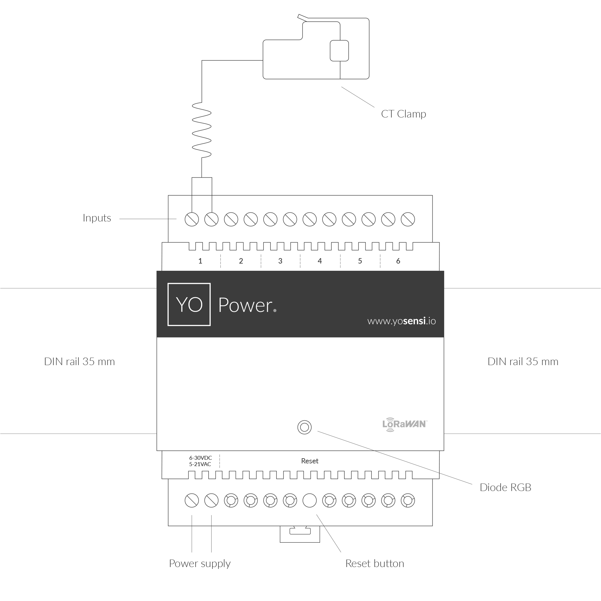
Figure 1. Device top view
Device sticker placed on the right side of the device enclosure contains information about model, version, LoRaWAN region and 3 parameters important in case of device identification and configuration:
- DEV EUI: 64-bit unique device identifier in a LoRaWAN network,
- DEV ADDR: address required to connect via ABP activation type to LoRaWAN,
- BLE MAC: Bluetooth physical address.
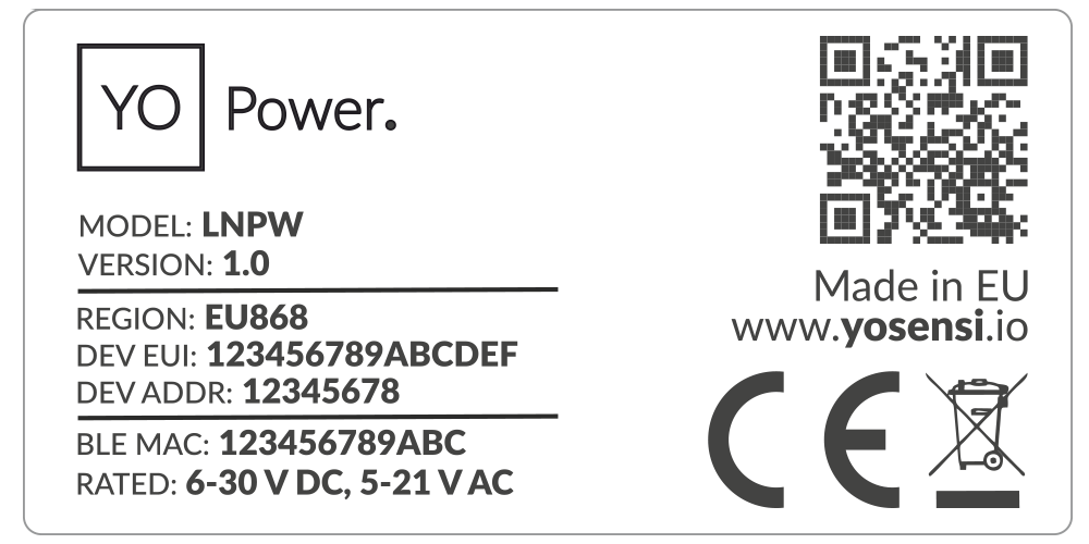
Figure 2. Device sticker
Features
- LoRaWAN Technology: Available in multiple versions with LoRa radio configured for various regions and ISM frequency bands (e.g., EU868, US915, AU915), it is compatible with both private and public LoRaWAN networks and supports connections via ABP (Activation by Personalization) or OTAA (Over-The-Air Activation).
- Bluetooth Low Energy (BLE): Enables easy configuration through a user-friendly JSON data exchange format, supports firmware updates via OTA (Over-the-Air), and boasts very low energy consumption.
- Current: Automatically switchable measurement ranges and specialized integrated circuits ensure exceptional precision and high accuracy.
- Energy meter: Calculates power for each connected electrical grid based on stored current measurements, sends LoRa packets with energy consumption data over defined intervals, and resets the energy meter value upon startup or device reset.
- Yosensi Management Platform: Provides a web tool for device configuration, firmware updates, and infrastructure management. Enables comprehensive monitoring of transmitted data and easy device management.
- Yosensi Mobile App: Effortlessly manage devices with features to register new ones, configure settings, perform firmware updates, view/send logs, and test LoRaWAN connectivity. Learn more in our detailed Yosensi App blog post.
Specifications
Physical
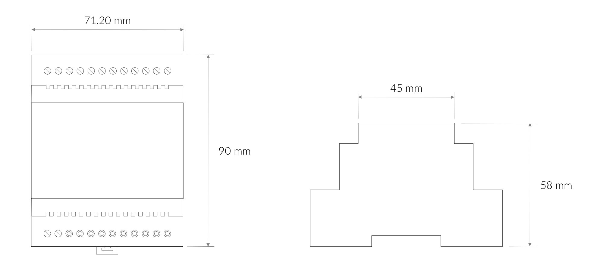
Figure 3. Dimensions of the device
Device
| Attribute | Description |
|---|---|
| Dimensions | Height: 90 mm Width: 71.20 mm (4-pole) Depth: 58 mm |
| Colour | Light Grey |
| Mounting method | 35 mm DIN rail standard |
| Enclosure material | Polycarbonate |
| Level of protection | IP20, UL94-VO |
| Weight | 125.2 g |
Operating Conditions
| Attribute | Description |
|---|---|
| Temperature | 0°C to 70°C |
| Humidity | 0 to 90% |
| Placement | Indoor use |
| Power supply | 6-30 V DC 5-21 V AC |
| Power consumption | Typical: 12 mA DC (12 V DC) Maximum: 120 mA DC (12 V DC) |
Measured Values
| Parameter | Measurement range | Accuracy |
|---|---|---|
| Current | CT Model: 50mA-100A | ±1% |
| CT Model: 40mA-160A | ±3% | |
| CT Model: 50mA-200A | ±3% | |
| CT Model: 50mA-400A | ±3% | |
| CT Model: 50mA-600A | ±3% | |
| CT Model: 50mA-800A | ±3% | |
| CT Model: 50mA-1000A | ±3% | |
| Energy meter | 0-230 V | Not given in datasheet |
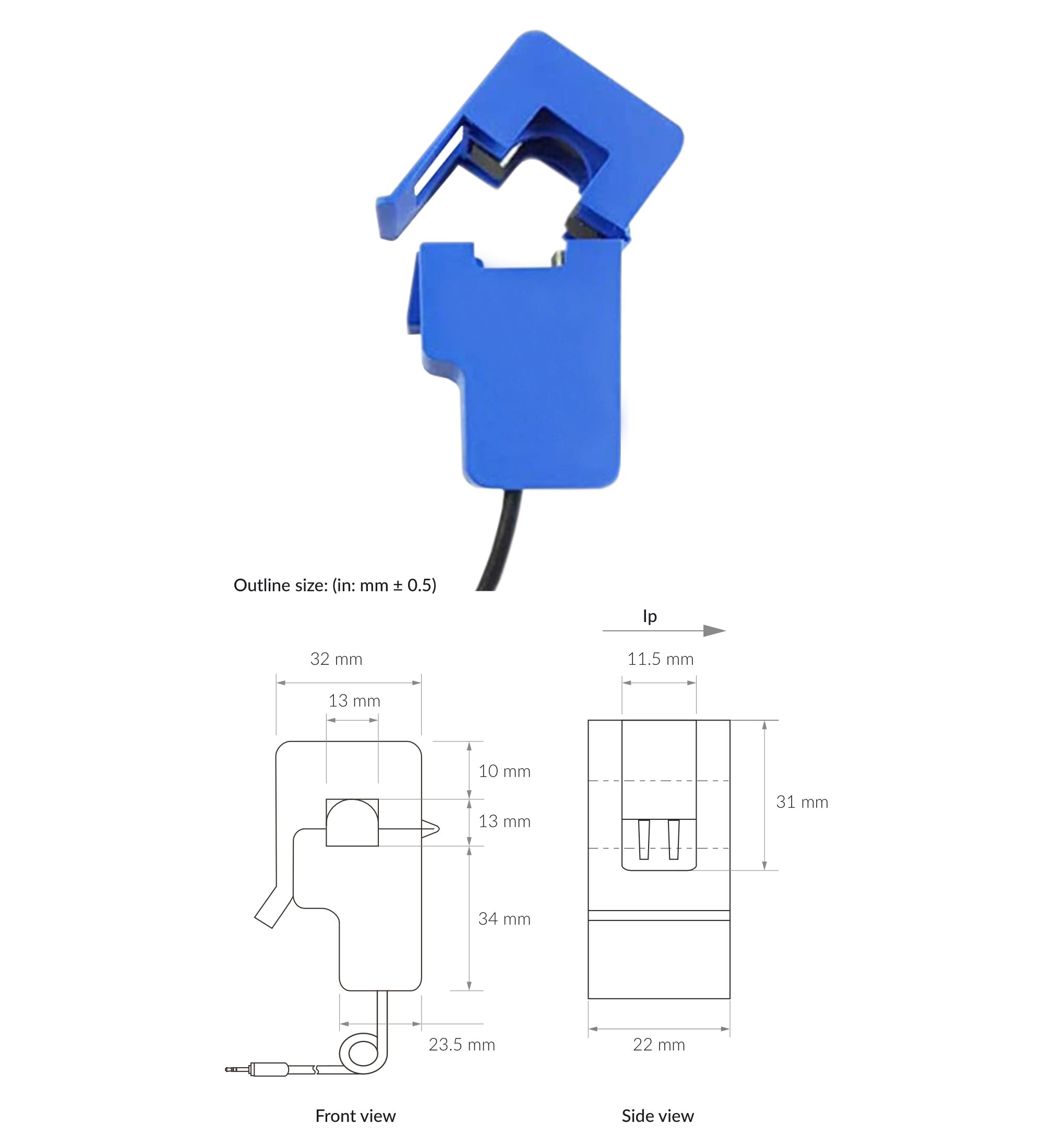
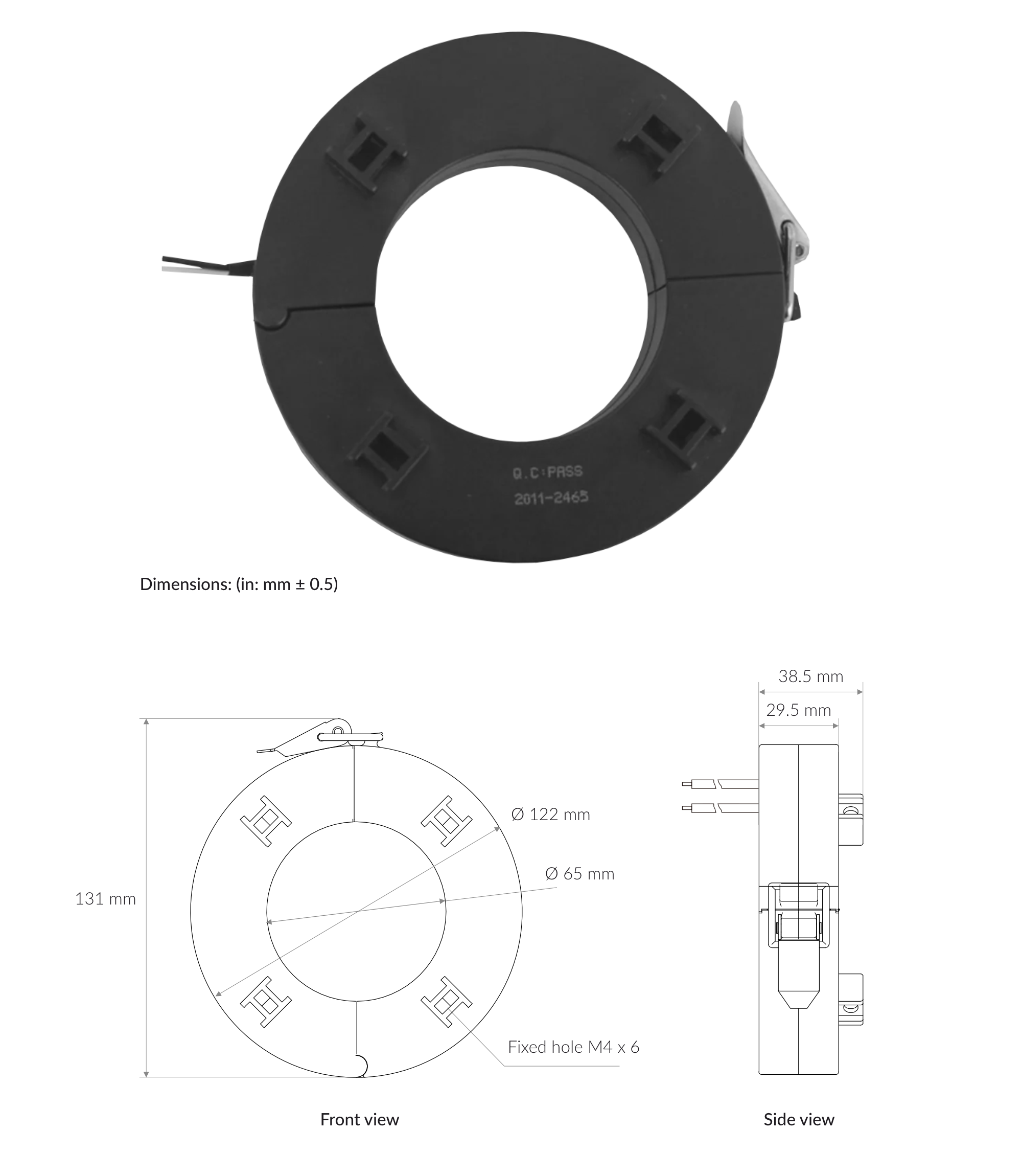
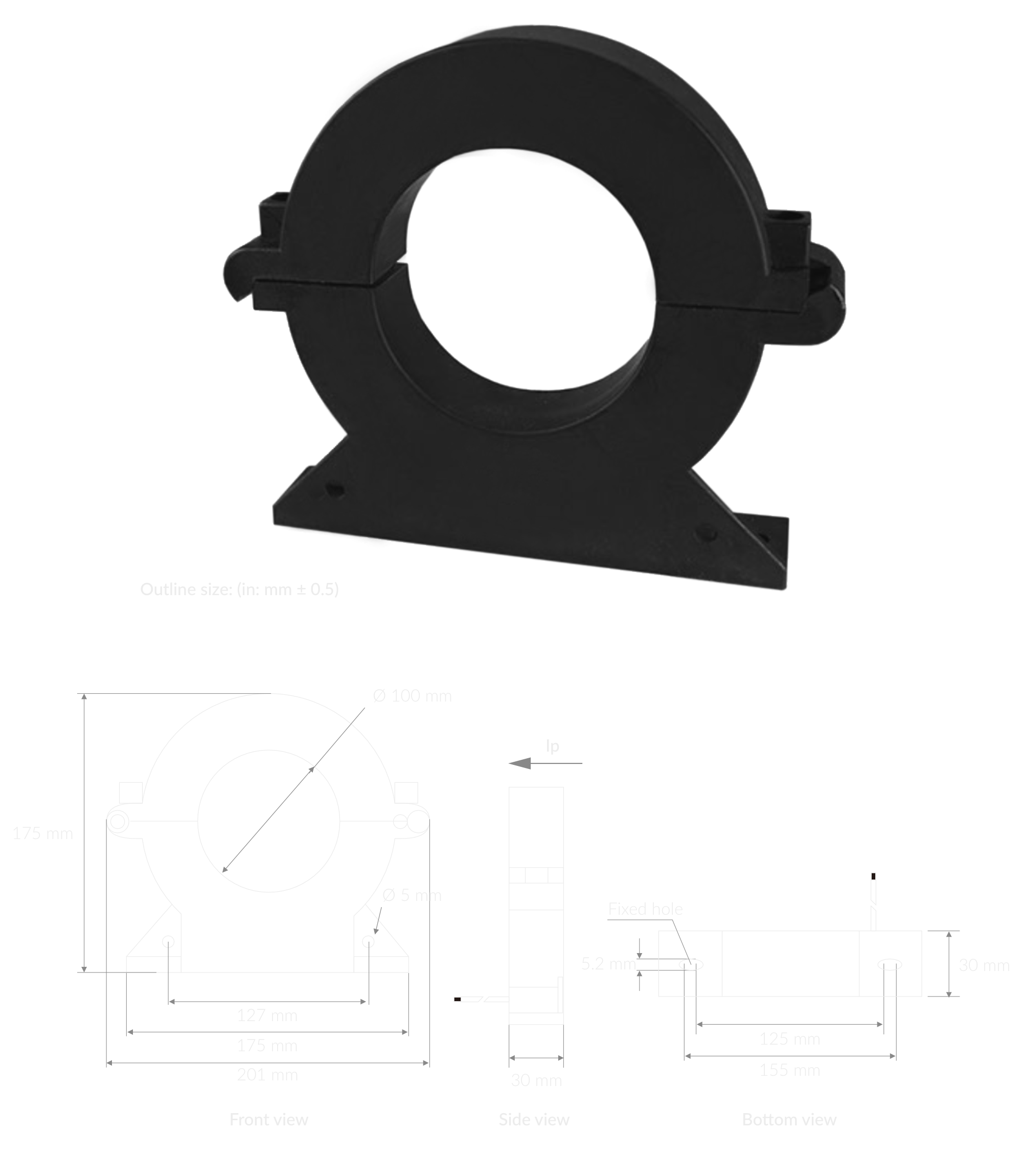
Current Transducers
Not sure which CT clamp to pick? Use the YO Power - CT Clamp: Amperage Calculator to estimate the expected current draw from a known load power and supply voltage.
CT - 100 A / 50 mA
| Attribute | Description |
|---|---|
| Working voltage | Phase voltage ≤ 720 |
| Working temperature | -25°C to 70°C |
| Frequency range | 50 Hz - 1 kHz |
| Input current | 100 A |
| Accuracy | ±1% |
| Max cable diameter | 13 mm |
| Weight | 50 g |
CT - 160 A / 50 mA
| Attribute | Description |
|---|---|
| Working voltage | Phase voltage ≤ 720 |
| Working temperature | -25°C to 60°C |
| Frequency range | 50 Hz - 60 Hz |
| Input current | 160 A |
| Accuracy | ±1% |
| Max cable diameter | 24 mm |
| Weight | 204 g |
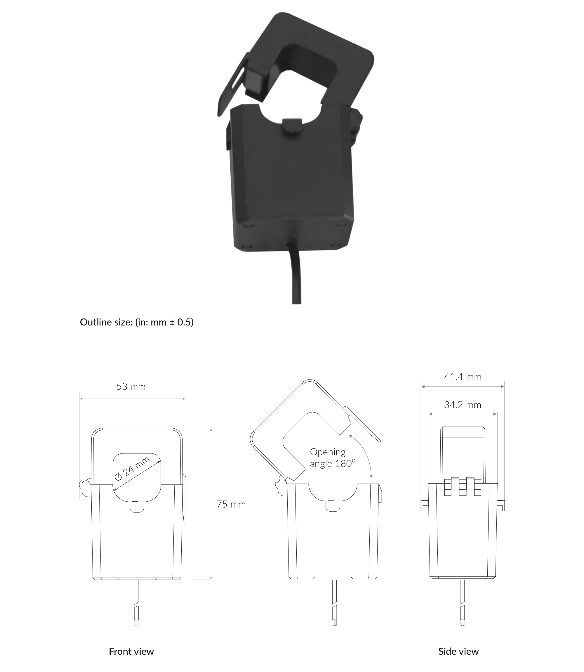
CT - 200 A / 50 mA
| Attribute | Description |
|---|---|
| Working voltage | Phase voltage ≤ 720 |
| Working temperature | -30°C to 65°C |
| Frequency range | 50 Hz - 60 Hz |
| Input current | 200 A |
| Accuracy | ±0.5% |
| Max cable diameter | 45 mm |
| Weight | 325 g |
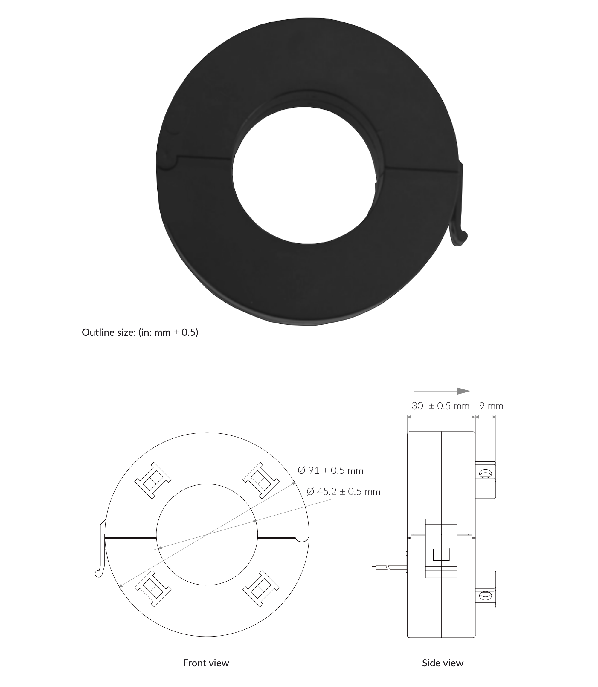
CT - 400 A / 50 mA
| Attribute | Description |
|---|---|
| Working voltage | Phase voltage ≤ 720 |
| Working temperature | -30°C to 65°C |
| Frequency range | 50 Hz - 60 Hz |
| Input current | 400 A |
| Accuracy | ±0.5% |
| Max cable diameter | 45 mm |
| Weight | 325 g |


CT - 600 A / 50 mA
| Attribute | Description |
|---|---|
| Working voltage | Phase voltage ≤ 720 |
| Working temperature | -30°C to 65°C |
| Frequency range | 50 Hz - 60 Hz |
| Input current | 600 A |
| Accuracy | ±0.5% |
| Max cable diameter | 45 mm |
| Weight | 325 g |


CT - 800 A / 50 mA
| Attribute | Description |
|---|---|
| Working voltage | Phase voltage ≤ 720 |
| Working temperature | -30°C to 65°C |
| Frequency range | 50 Hz - 60 Hz |
| Input current | 800 A |
| Accuracy | ±1% |
| Max cable diameter | 65 mm |
| Weight | 592 g |
CT - 1000 A / 50 mA
| Attribute | Description |
|---|---|
| Working voltage | Phase voltage ≤ 720 |
| Working temperature | -20°C to 60°C |
| Frequency range | 50 Hz - 1 kHz |
| Input current | 1000 A |
| Accuracy | ±1% |
| Max cable diameter | 100 mm |
| Weight | 1070 g |

Controls and Indicators
LED Status Indicator
YO Power communicates its current behaviour to the user by RGBW LED placed on the top.
Diode statuses interpretation
| Behavior | Colour | Status |
|---|---|---|
| Single flash | Green | General: device is working correctly (power and memory). |
| Single flash | Red | General: device is working incorrectly (power and memory). LoRaWAN communication: failed to receive an acknowledgement from LoRaWAN Server within specified timeout. |
| Single flash | White | LoRaWAN communication: LoRaWAN frame sent / confirmation from LoRaWAN Server after receiving the frame. |
| Slow flashing | Blue | BLE communication: connection to the device via BLE (configuration). |
| Rapid flashing | Blue | LoRaWAN communication: connecting to LoRaWAN network. |
Buttons
The YO Power features a reset button located on the PCB, labeled "Reset". To reboot the device, simply press the button briefly.
Installation
Package Contents
- Device.
- Warranty card.
Safety Precautions
Go to the Safety Precautions section to see important information on handling, disposal and maintenance.
Installation Guide
- Mount the device on a 35 mm DIN rail.
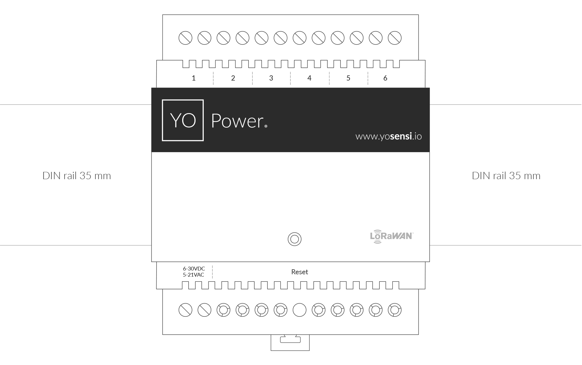
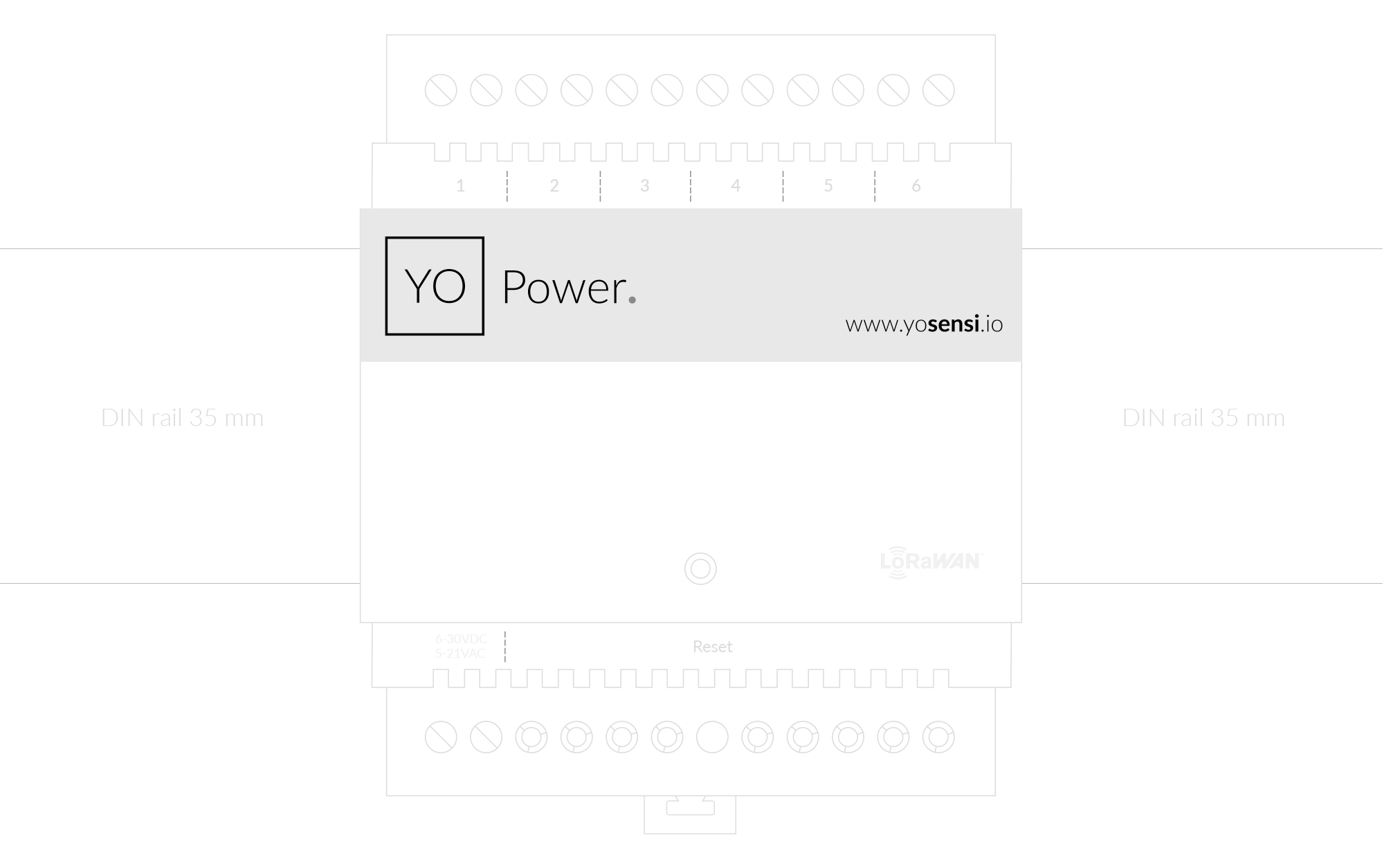
Figure 11. Device mounting instructions
- Connect the inputs to the individual channels of the device according to the polarity shown on the enclosure label.
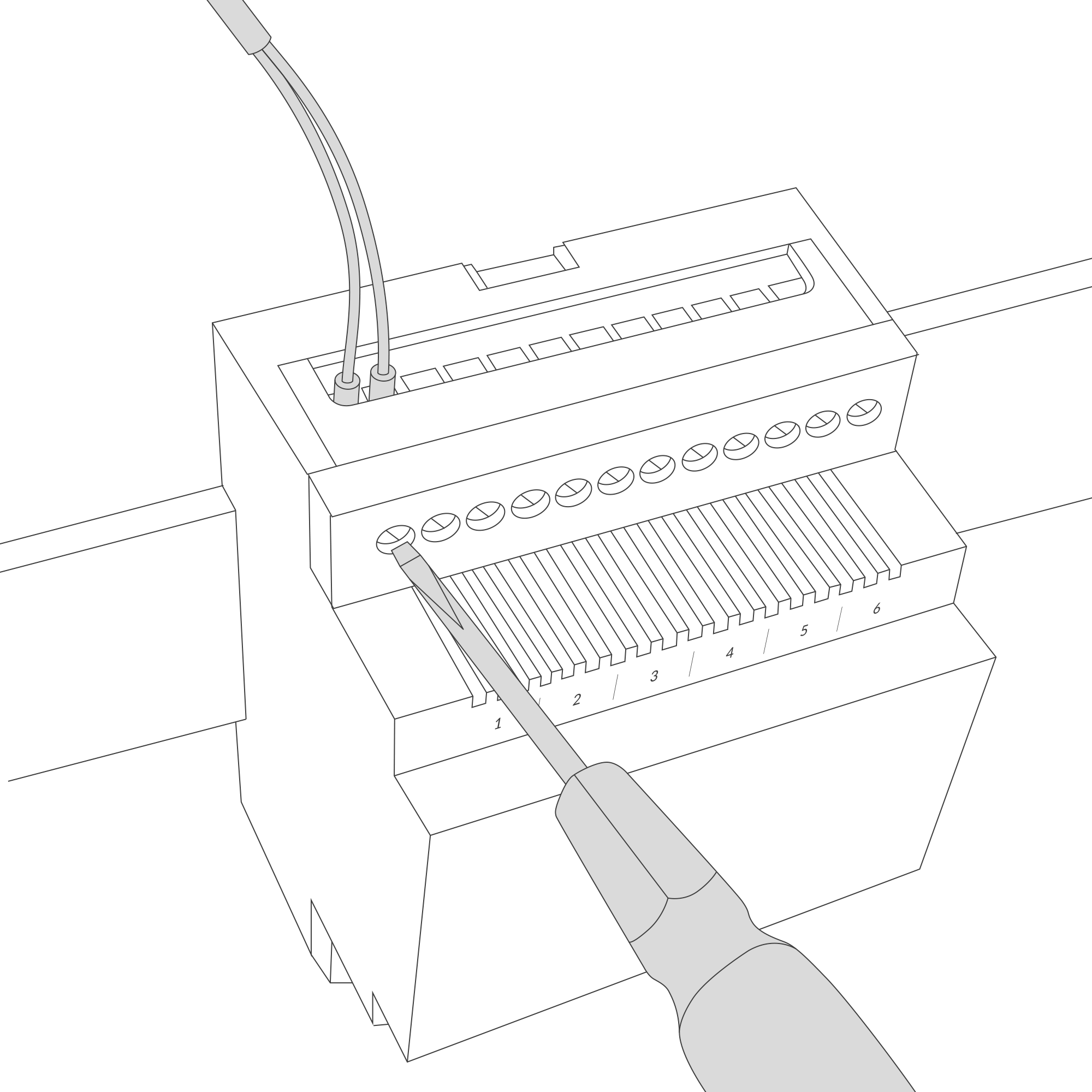
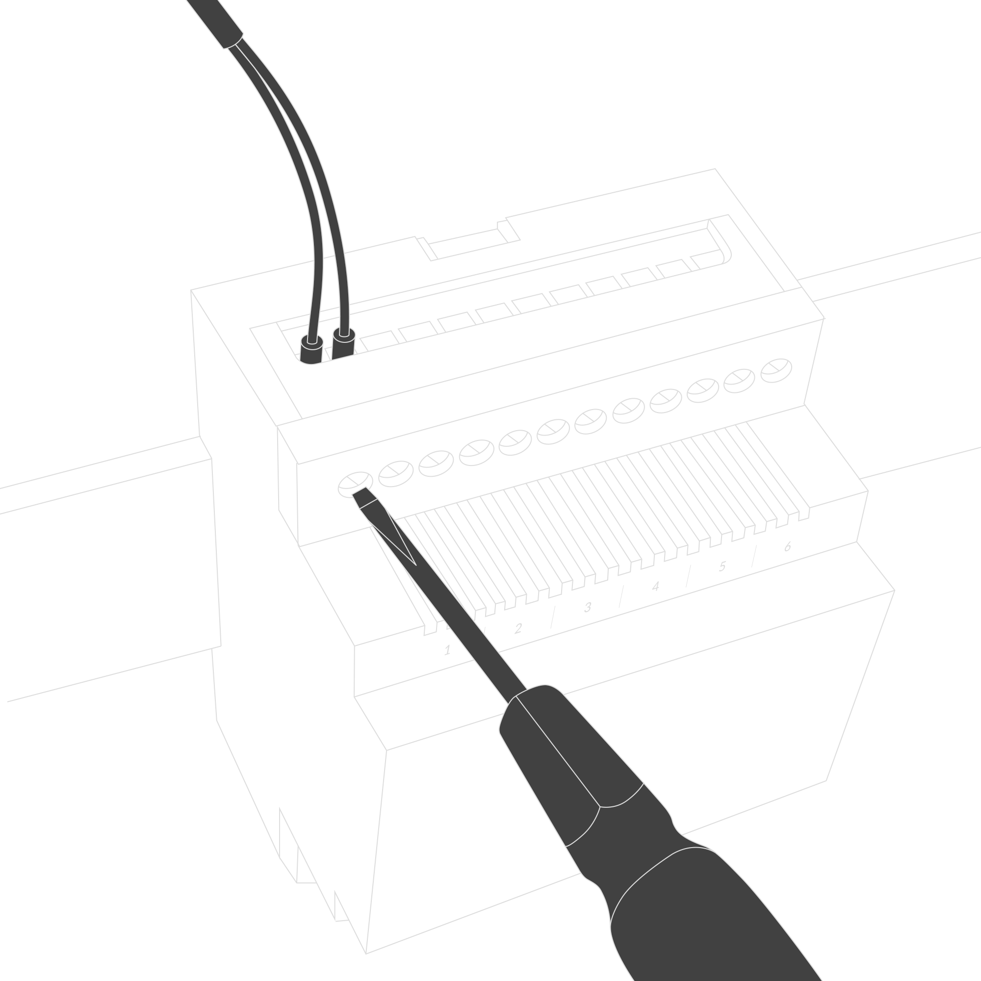
Figure 12. Connect the inputs to the individual channels of the device
- Fasten the current clamps around the wires in which the current is to be measured (a clamp should be placed around one wire).


Figure 13. Instruction on how to fasten the current clamps around the wires
- Screw the power supply wires to the device regardless of polarity (6-30 V DC, 5-21 V AC).
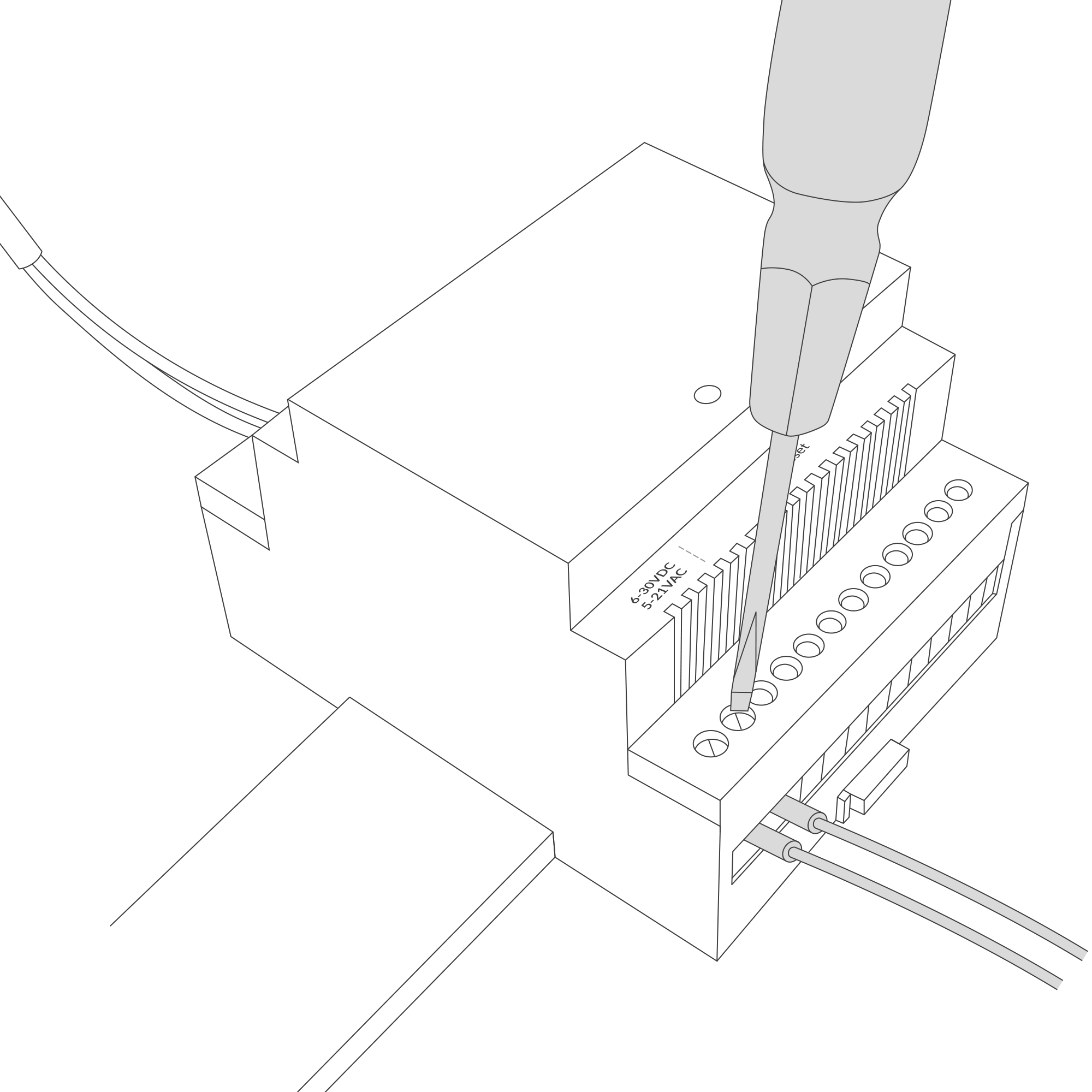
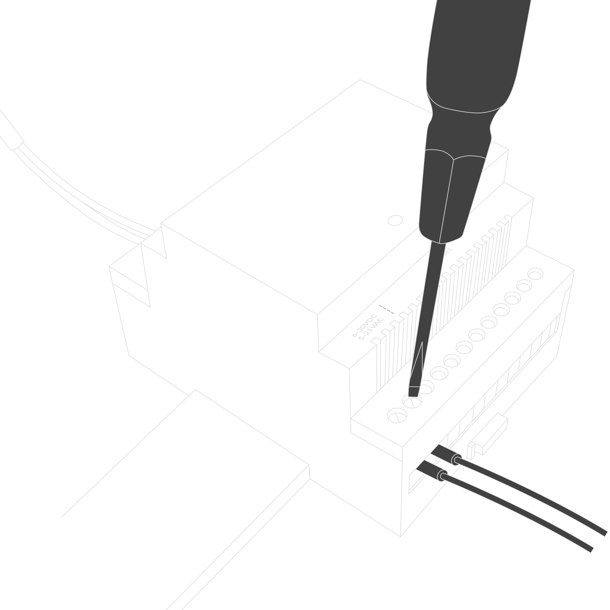
Figure 14. Instruction on how to connect the power to the device
- After connecting the wires, diodes should behave as it is described on LED Status Indicator.
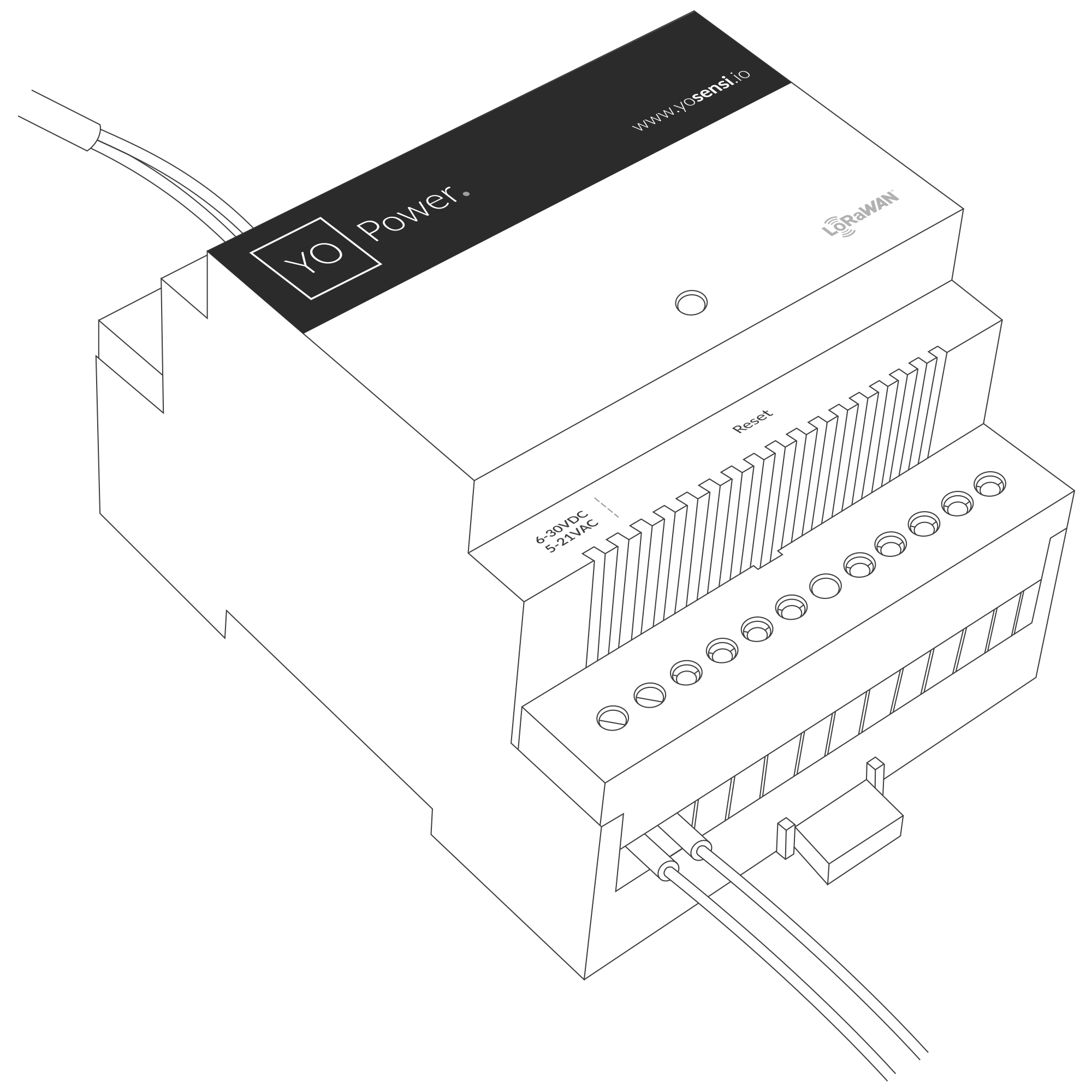
Figure 15. Final look of the device
Configuration
Configurable Parameters
A few parameters must be set before sending data to the gateway. The default firmware is configured in OTAA mode with predefined deveui, appkey (OTAA) and appskey, nwkskey (ABP).
Configuration of the device is stored in a JSON file divided into the following sections:
- info (generic, read only): information about the device,
- general (generic): general device settings,
- lorawan (generic): configuration data for LoRaWAN connection,
- ble (generic): Bluetooth settings,
- device (dynamic): individual configuration for a specific device (this section’s structure differs for each device),
- channels (dynamic): each channel of YO Power with specific configuration of current stream energy meter, voltage on electricity grid,
Sample configuration file for the YO Power device.
{
	"info": {
		"devmodel": "LNPW",
		"fwver": "4.0.3",
		"loraradio": "SX1261",
		"lorawanver": "1.0.2",
		"loraregion": "EU868",
		"blemacaddr": "0123456789ab"
	},
	"general": {
		"rtcstate": "disable"
	},
	"lorawan": {
		"subband": 1,
		"retrycnt": 3,
		"nwktype": "public",
		"acttype": "otaa",
		"otaa": {
			"deveui": "0123456789abcdef",
			"appeui": "fedcba9876543210",
			"appkey": "000102030405060708090a0b0c0d0e0f",
			"trials": 3
		},
		"abp": {
			"devaddr": "01234567",
			"nwkskey": "0123456789abcdef0123456789abcdef",
			"appskey": "000102030405060708090a0b0c0d0e0f"
		}
	},
	"ble": {
		"power": 0,
		"interval": 100
	},
	"device": {
		"measinterval": 60,
		"measthreshold": 10,
		"ch1cttype": "50mA-100A",
		"ch2cttype": "50mA-100A",
		"ch3cttype": "50mA-100A",
		"ch4cttype": "50mA-100A",
		"ch5cttype": "50mA-100A",
		"ch6cttype": "50mA-100A",
		"energysendinterval": 1200,
		"channels": [
			{
			"channel": 1,
			"currentstream": "on",
			"energymeter": "on",
			"voltage": 230,
			"powerfactor": 0.90,
			"clearenergy": "no"
			},
			{
			"channel": 2,
			"currentstream": "on",
			"energymeter": "on",
			"voltage": 230,
			"powerfactor": 0.90,
			"clearenergy": "no"
			},
			{
			"channel": 3,
			"currentstream": "on",
			"energymeter": "on",
			"voltage": 230,
			"powerfactor": 0.90,
			"clearenergy": "no"
			},
			{
			"channel": 4,
			"currentstream": "on",
			"energymeter": "on",
			"voltage": 230,
			"powerfactor": 0.90,
			"clearenergy": "no"
			},
			{
			"channel": 5,
			"currentstream": "on",
			"energymeter": "on",
			"voltage": 230,
			"powerfactor": 0.90,
			"clearenergy": "no"
			},
			{
			"channel": 6,
			"currentstream": "on",
			"energymeter": "on",
			"voltage": 230,
			"powerfactor": 0.90,
			"clearenergy": "no"
			}
		]
	}
}
OTAA & ABP
| OTAA | ABP |
|---|---|
| Device EUI | Device Address |
| Application EUI | Network Session Key |
| Application Key | Application Session Key |
| Number of Trials |
Generic Parameters
Click here to see the generic parameters for Yosensi devices.
Parameters
Device Parameters
| Name | Description | Possible Values | Default Value | Read/Write |
|---|---|---|---|---|
| measinterval | Measuring and sending interval LoRa [s] | 601-999999 | 300 | R/W |
| measthreshold | Measurement threshold for each channel | 1-9999 | 10 | R/W |
| ch1cttype-ch6cttype | Number of channels with different possible CT clamps | 50mA-100A, 40mA-160A, 50mA-200A, 50mA-400A, 50mA-600A, 50mA-800A, 50mA-1000A | 50mA-100A | R/W |
| energysendinginterval | Interval of time which sends information about measured energy [s] | 600-999999 | 3600 | R/W |
| currentstream | Streaming of current flow on electrical networks | on, off | on | R/W |
| energymeter | Energy meter for each channel [kWh] | on, off | on | R/W |
| voltage | Voltage for each channel of the electricity grid [V] | 1-1000 | 230/110 | R/W |
| powerfactor | Power factor | 0-1 | 0.90 | R/W |
| clearenergy | Reset of stored energy meter on each channel | no, yes | no | R/W |
| ||||
Parameters description
- rtcstate: used for enabling/disabling the real-time clock (RTC) inside the device. The RTC is used for timestamping the measurements.
- nwktype: used for setting the device in public or private network type.
- acttype: used for setting the device in ABP or OTAA mode.
- deveui, … , appskey: predefined addresses and keys, these parameters are generated using multiple IDs specific to the particular MCU and are unique for each device. They can be changed if needed.
- interval: determines the interval of sending broadcast packets, used to connect to every BLE receiver around the device.
- subband: used for setting the communication frequency sub-band in LoRaWAN.
- retrycnt: number of retries to send a LoRa packet if the acknowledgement is not received from the LoRaWAN server.
- measinterval: measurement interval [s] between sending LoRa packets.
- measthreshold: measurement threshold for each channel. If the current value between the previous measurement and the next differs by a value of ‘meastreshold’, it queues this data for sending. The current difference is reported in subsequent LoRa packets along with the measurement time.
- ch1cttype…ch6cttype: 6 different channels to which the current transducer clamps can be connected. For correct measurements and measuring ranges, the possible value must coincide with the sensor connected to the device.
- energysendinterval: Interval of time which sends information about calculated energy in electrical network [s]. The minimum time interval between measurement is 600 s.
- currentstream: YO Power monitor current flow on each phase. This parameter activates or deactivates streaming and monitoring current on Yosensi Management platform.
- energymeter: This parameter activates or deactivates the energy meter. Due to current flow on each phase YO Power stores information about current. Algorithms built in the device calculate energy consumption and send a LoRa packet with a given parameter ‘energysendinterval’.
- voltage: voltage of electricity grid [V]. This parameter differs for LoRa regions. YO Power with firmware for EU868 is 230 V, AU915 220 V and US915 is 110 V.
- powerfactor: power factor is the ratio of working power, measured in kilowatts (kW), to apparent power, measured in kilovolt amperes (kVA). Apparent power, also known as demand, is the measure of the amount of power used to run machinery and equipment during a certain period. Default value is 0.9.
- clearenergy: parameter that clears the value of measured energy consumption.
Outlier detection mechanism
The outlier detection mechanism uses the measthreshold parameter to assess the sensitivity range for data points. When all values fall within this range, only the first and last measurements are included in the payload. If out-of-range values are detected, additional data points are added to the payload. In cases where the number of data points exceeds the payload capacity, the system sends the remaining points in subsequent payloads at a reduced interval, overriding the configured measinterval value.
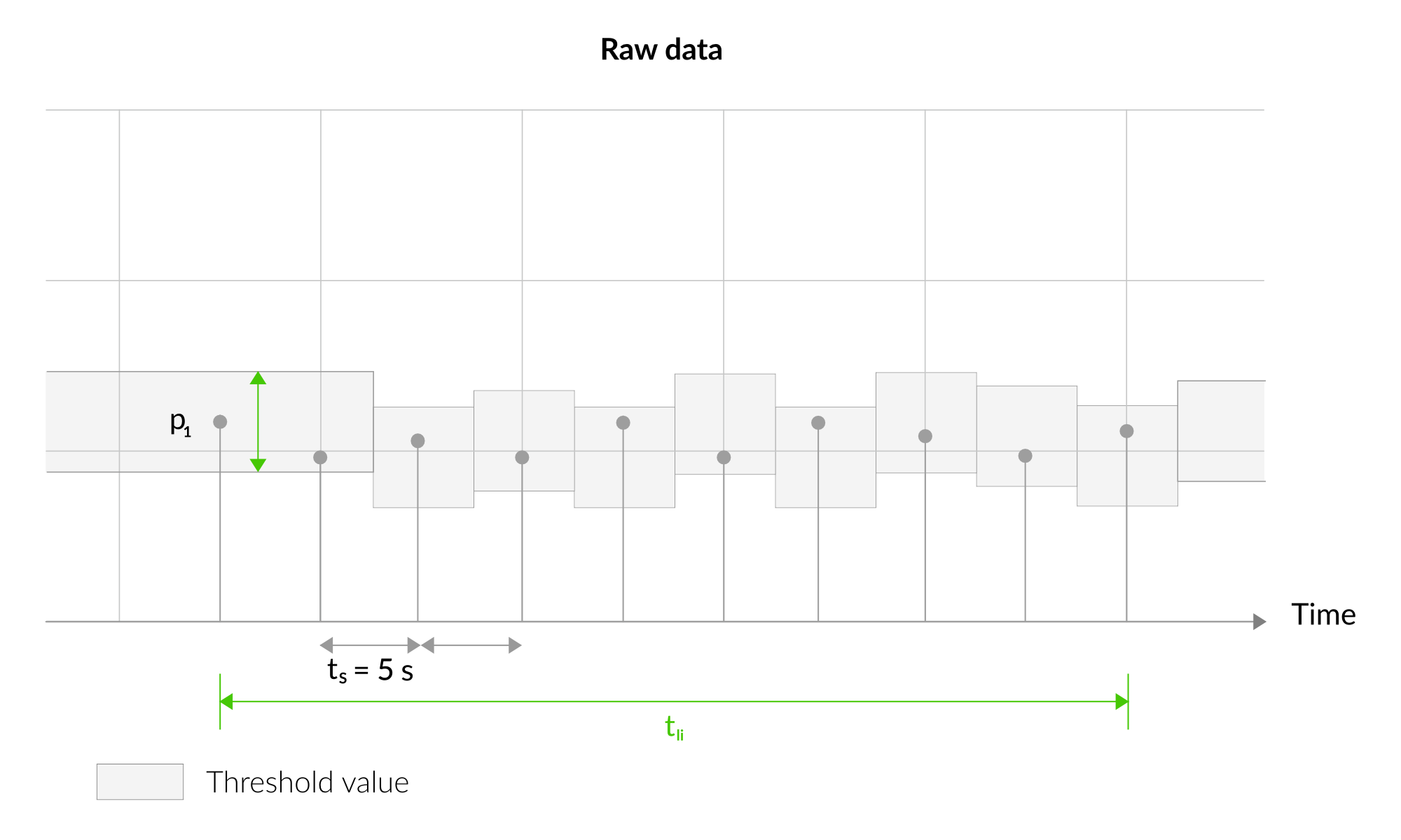
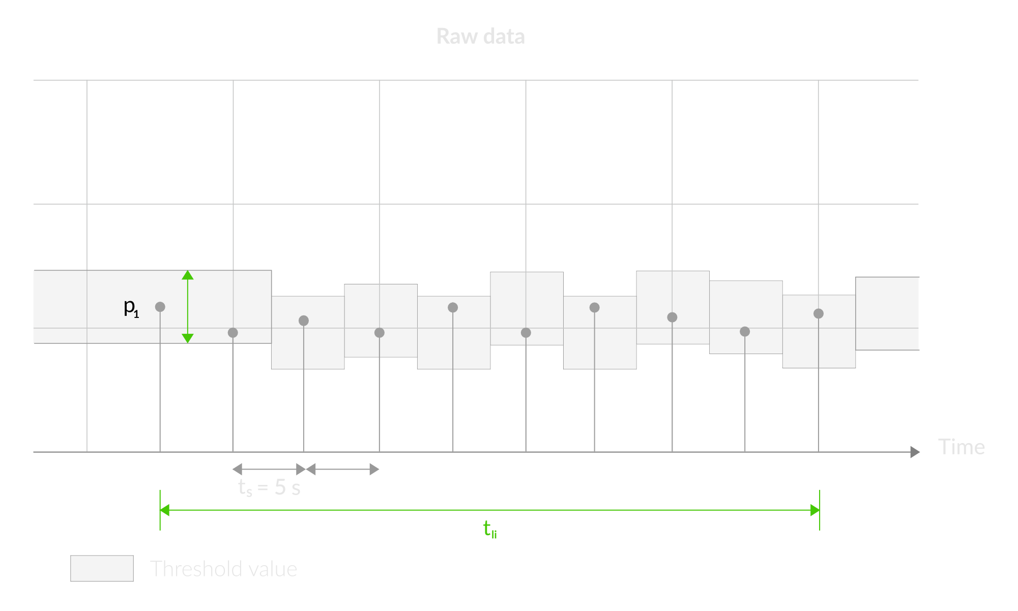
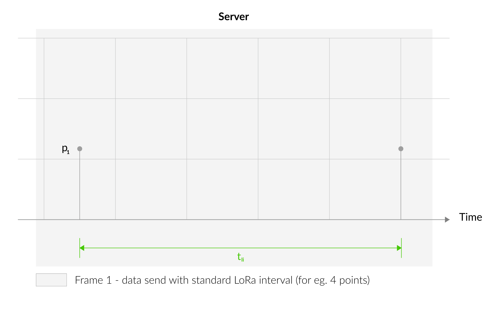
Figure 16. Outlier detection mechanism 1
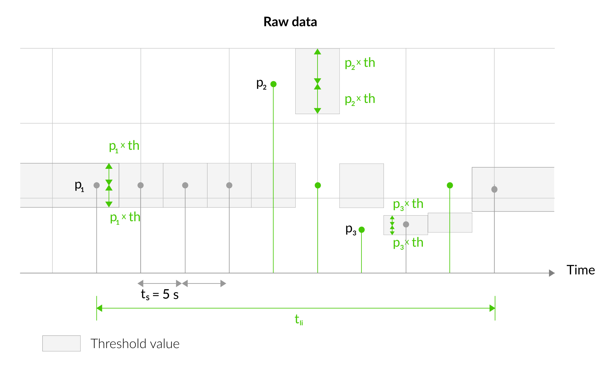
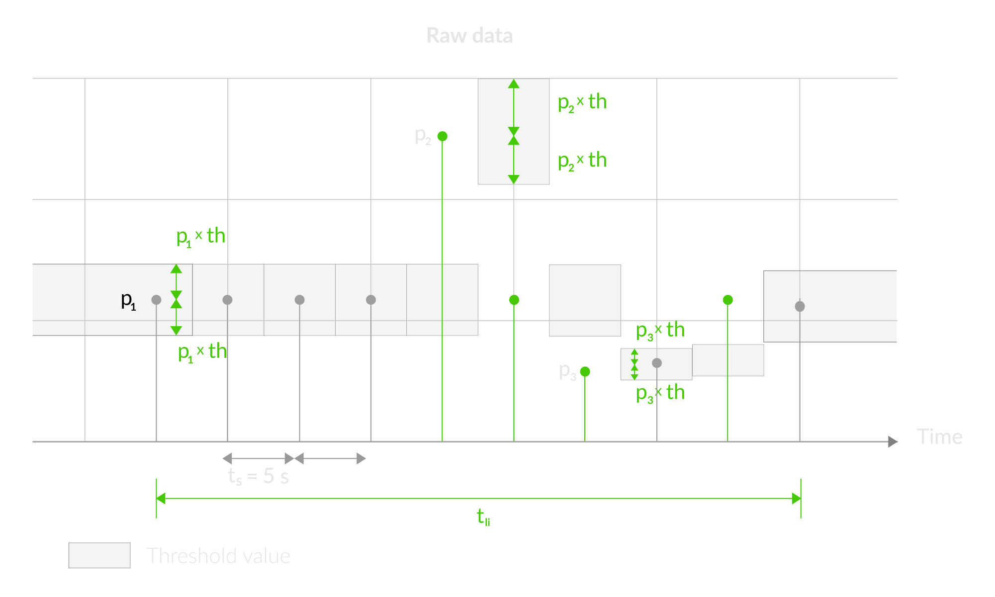
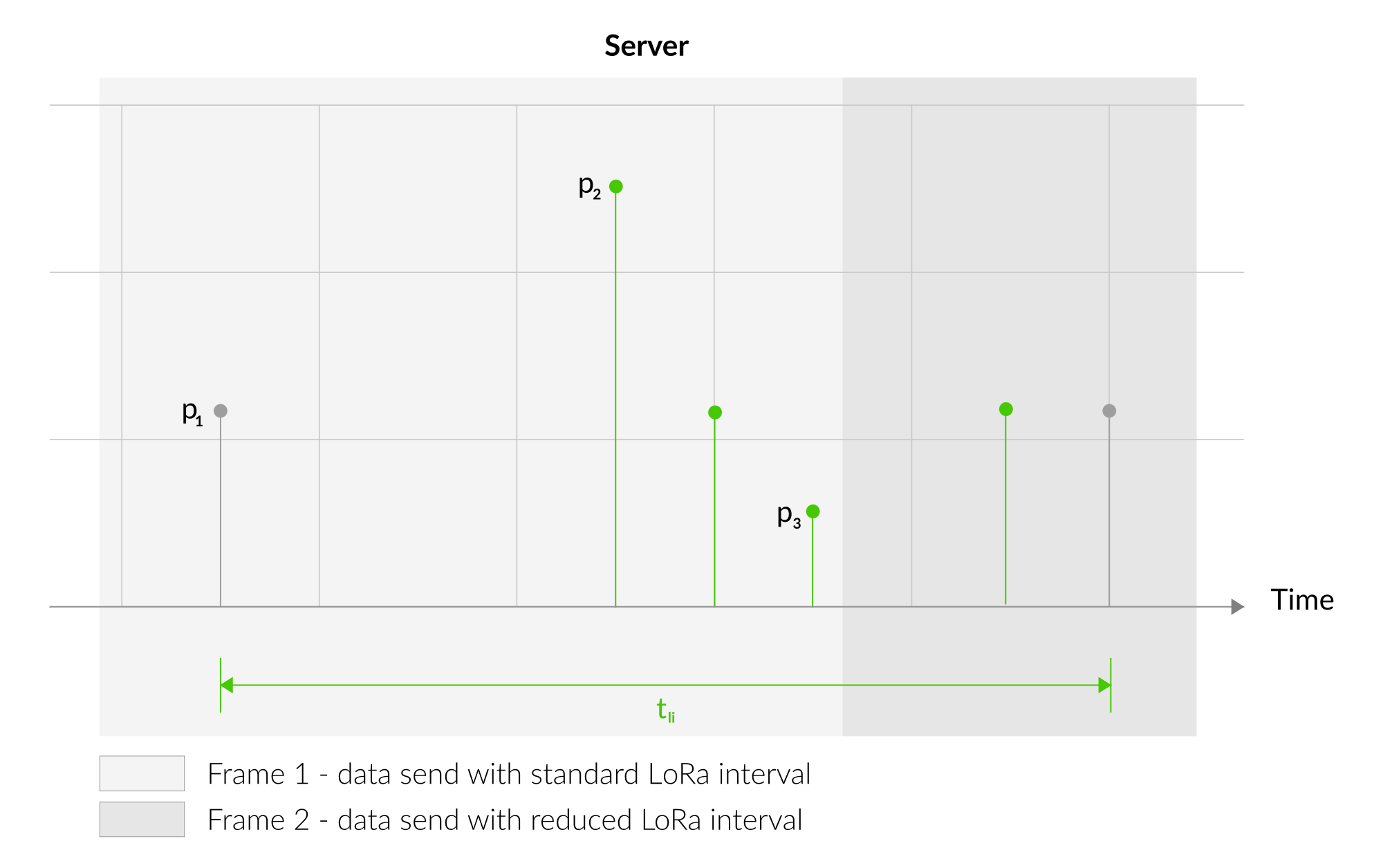
Figure 17. Outlier detection mechanism 2
Downlink message
You can remotely adjust certain parameters by sending a downlink message through our platform. Simply navigate to the "COMMANDS" section for the selected device.
Update Measurement Interval
It is possible to change the measurement interval (measinterval) by using downlink. Information about changing the parameter will be sent from the server via the gateway.
Example of Downlink Message:
- Prefix:
0x03 - Measurement Index:
0x00 - Data (up to 4 bytes in hex):
0258
Sample Downlink: 0x03000258 - Sets a measurement interval of 600 seconds (10 minutes).
Click here to see how to connect a node using the Yosensi Management Platform.
See how to configure a node in Yosensi Management Platform
Check how to adopt and configure a node via the Yosensi App.
Take a look at the list of frequency plans used in Yosensi.
This datasheet describes the payload protocol developed by Yosensi for communicating with our devices.
Payload Decoder
If you want to connect to your own server, it is necessary to decode the specific payload for each device. To accomplish this, a payload decoder is required, which can be downloaded using the following link: Payload decoder. You can also use our integrated Payload Decoder here. Extended documentation of the protocol can be found in the Payload description on our website.
Compliance Statements
To view or download the Declaration of Conformity for YO Power go here