YO Vibration Monitor
Overview
Description
YO Vibration Monitor is designed for monitoring vibrations in electric motors and other machinery. It features a vibration sensor with an accelerometer and temperature sensor, along with internal temperature and relative humidity sensors. Using 3-axis composite measurements, the device detects vibrations and transmits data via LoRaWAN. Its battery-powered design ensures non-invasive installation without the need for additional cables. Configurable parameters include minimum/maximum analysis frequency, detection threshold, activation state, measurement delay, inactivity time, and a clearable counter. Ideal for predictive maintenance, the YO Vibration Monitor enables remote, continuous monitoring, replacing traditional inspections and improving the reliability of machines, production lines, and similar systems.
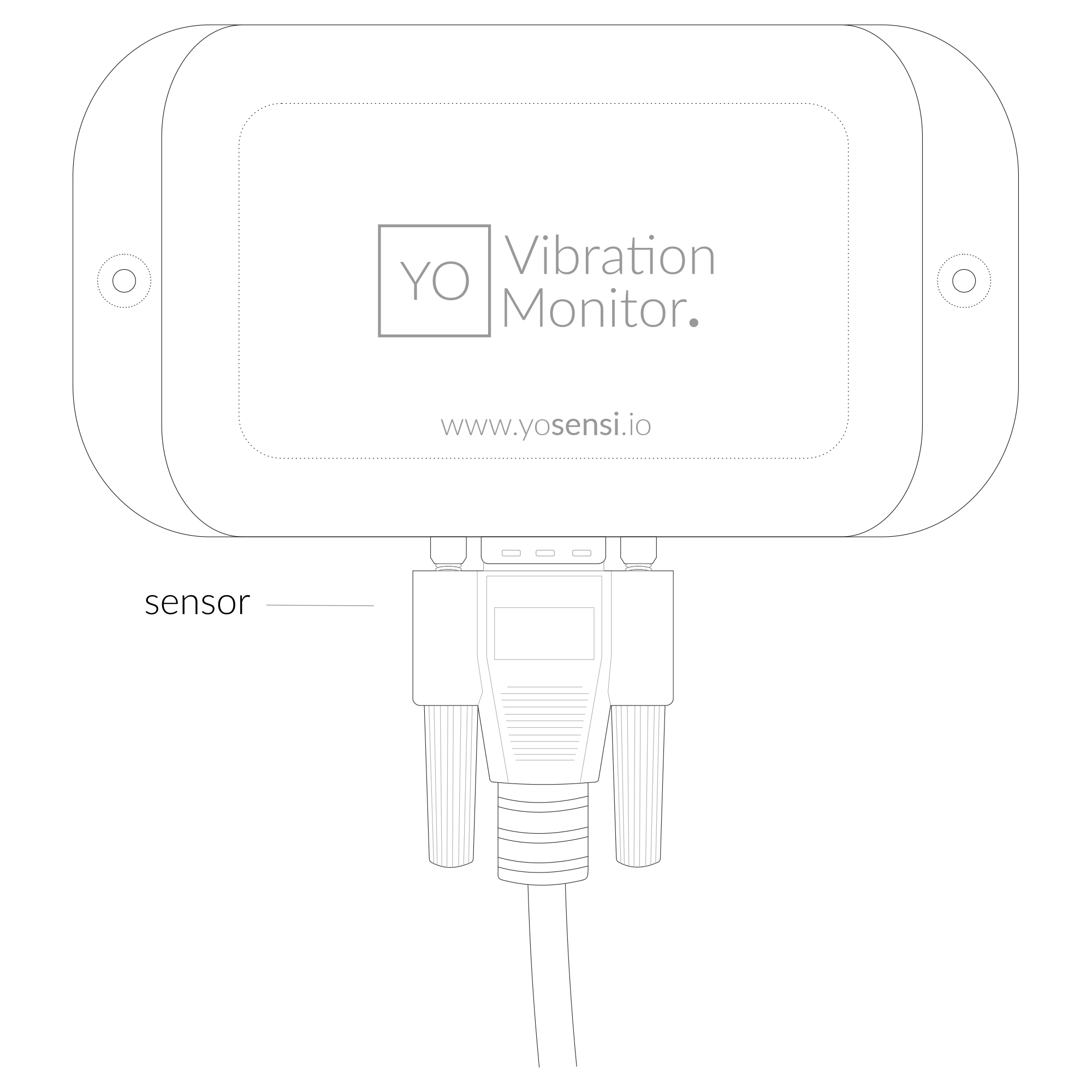
Figure 1. Device top view
Device sticker placed on the right side of the device enclosure contains information about model, version, LoRaWAN region and 3 parameters important in case of device identification and configuration:
- DEV EUI: 64-bit unique device identifier in a LoRaWAN network,
- DEV ADDR: address required to connect via ABP activation type to LoRaWAN,
- BLE MAC: Bluetooth physical address.
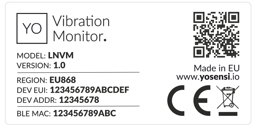
Figure 2. Device sticker
Features
- LoRaWAN Technology: Available in multiple versions with LoRa radio configured for various regions and ISM frequency bands (e.g., EU868, US915, AU915), it is compatible with both private and public LoRaWAN networks and supports connections via ABP (Activation by Personalization) or OTAA (Over-The-Air Activation).
- Bluetooth Low Energy (BLE): Enables easy configuration via a user-friendly JSON data exchange format. Supports firmware updates via OTA (Over-the-Air). Very low energy consumption
- Battery-Powered: Equipped with 3x AA lithium batteries featuring very low self-discharge, ensuring long-term operation without the need for an external power supply.
- Temperature and Relative Humidity: Measures temperature and relative humidity within the device enclosure, providing valuable insights into the surrounding environment.
- Vibration sensor: Equipped with a 3-axis accelerometer, the sensor detects and measures vibrations with high precision, enabling real-time monitoring of machinery and early detection of potential issues to support predictive maintenance.
- Yosensi Management Platform: Provides a web tool for device configuration, firmware updates, and infrastructure management. Enables comprehensive monitoring of transmitted data and easy device management.
- Yosensi Mobile App: Effortlessly manage devices with features to register new ones, configure settings, perform firmware updates, view/send logs, and test LoRaWAN connectivity. Learn more in our detailed Yosensi App blog post.
- Configurable Analysis Range: Define minimum and maximum vibration analysis frequency.
- Threshold Setting: Adjust vibration detection sensitivity in [g].
- Active State Control: Enable or disable vibration detection feature.
- Measurement Delay: Set a delay [s] before measurement after detecting vibration.
- Inactivity Timer: Define inactivity time [s] before rechecking threshold.
- Clearable Counter: Reset persistent vibration counter when needed.
Specifications
Physical
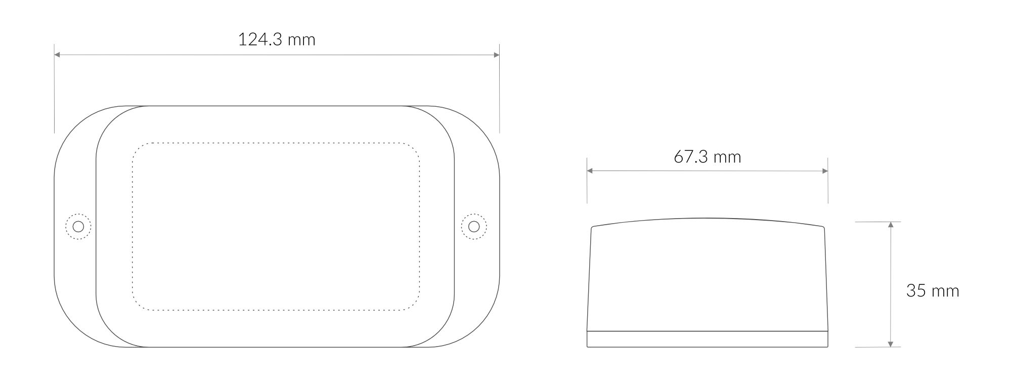
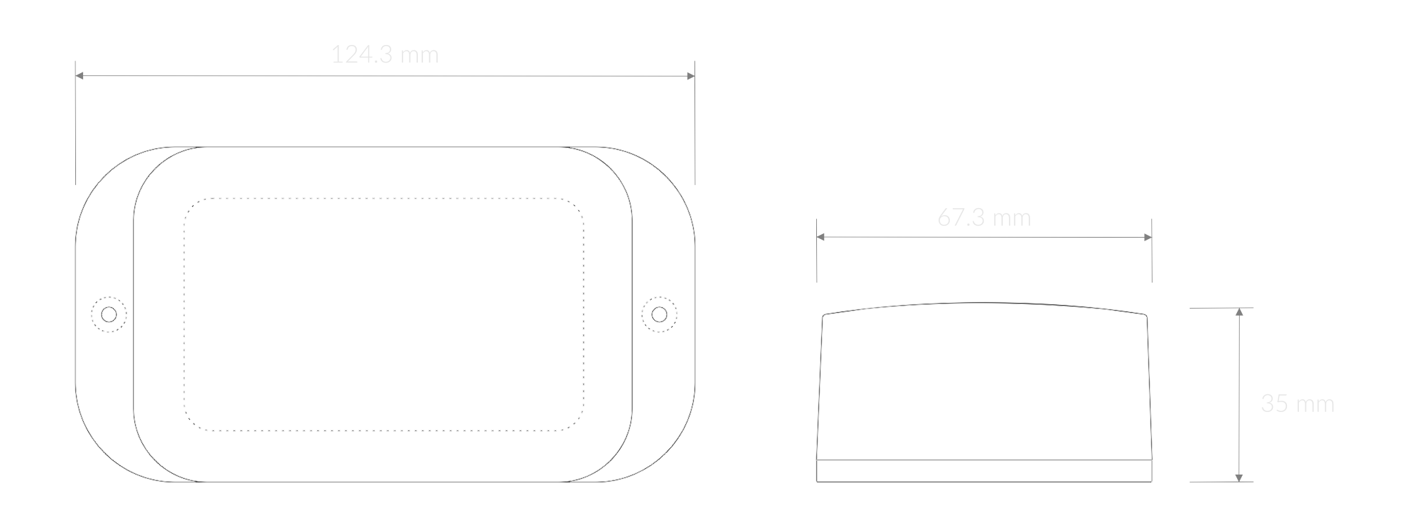
Figure 3. Dimensions of the device
Device
| Attribute | Description |
|---|---|
| Dimensions | Height: 35 mm Width: 67,3 mm Depth: 124,3 mm |
| Colour | White |
| Mounting method | Horizontal Vertical (can be screwed to the wall) |
| Enclosure material | ABS |
| Level of protection | IP40 |
| Weight | 220 g (without batteries, incl. sensor) |
Vibration sensor
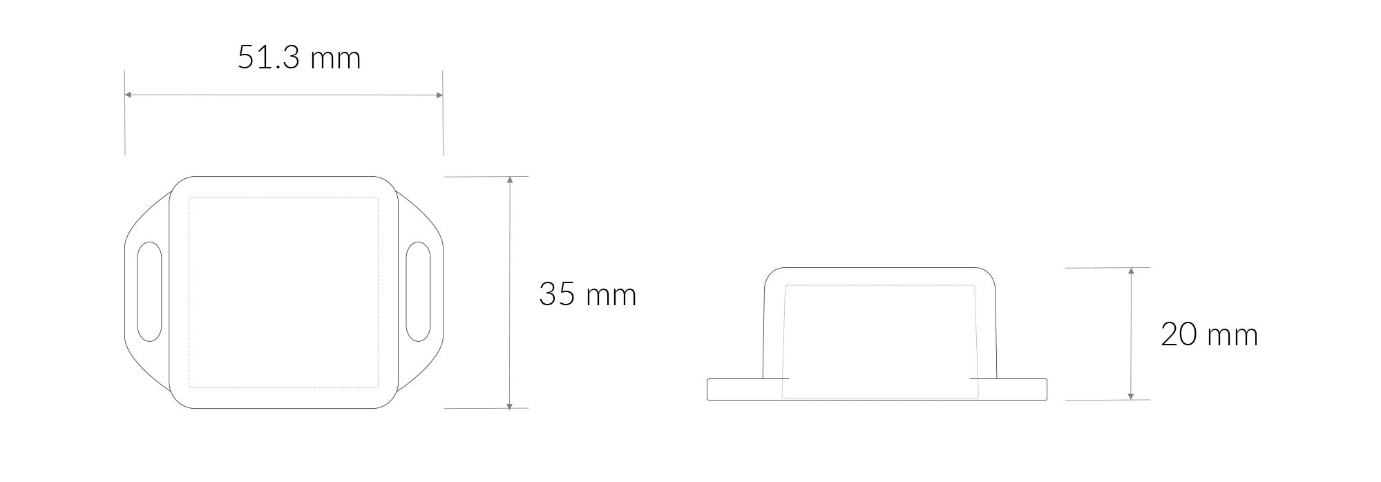
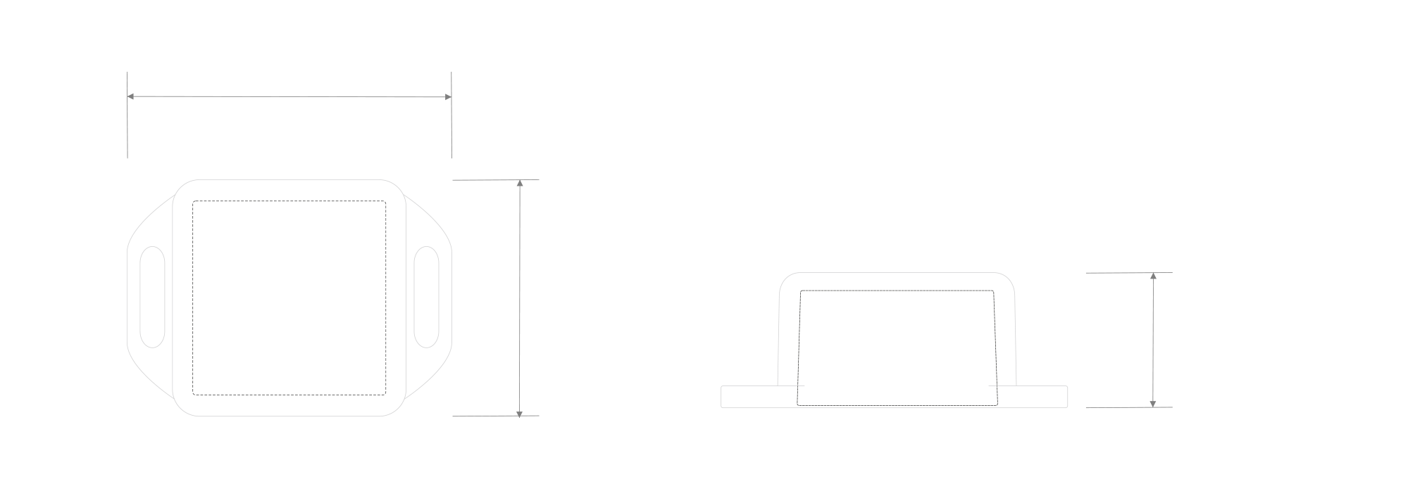
Figure 4. Vibration sensor
| Attribute | Description |
|---|---|
| Dimensions | Height: 35 mm Width: 35 mm Depth: 20 mm |
| Colour | Grey |
| Cable length | 1 m |
| Mounting method | Magnet Mounting (default) Internal Thread Mounting External Thread Mounting Mounting Bracket |
| Enclosure material | ABS |
| Level of protection | IP67 |
| Weight | 45 g |
Operating Conditions
| Attribute | Description |
|---|---|
| Temperature | 0°C to 70°C |
| Humidity | 0 to 90% |
| Placement | Indoor use |
| Power supply | 3 x LR6 (AA) battery (3 x 1,5 V) |
| Power consumption | Maximum: 120 mA DC (4,5 V DC) |
Measured Values
| Parameter | Measurement range | Accuracy |
|---|---|---|
| Temperature | -40°C to 125°C | ±0.2°C (5°C to 60°C) |
| Relative humidity | 0% to 100% | ±2% (20% to 80%) |
| Temperature external | -40°C to 125°C | ±0.2°C (5°C to 60°C) |
| XYZ Deviation | 0 to 10 | 0.01 |
| XYZ Kurtosis | -3 to 3 | 0.01 |
| XYZ Velocity RMS | 0 to 45 | 0.1 mm/s |
| XYZ Peak-to-Peak Displacement | 0 to 10000 | 1 μm |
| XYZ Crest factor | 0 to 160 | 0.01 |
| XYZ Peak | 0 to 16 g | 0.001 g |
| XYZ RMS | 0 to 16 g | 0.001 g |
| XYZ Skewness | -3 to 3 | 0.01 |
| XYZ Peak Frequency | 0 to 10000 Hz | 0.01 Hz |
| State | 0-1 | - |
| Counter | 0-2147483647 ( int32 ) | - |
Controls and Indicators
LED Status Indicator
YO Vibration Monitor communicates its current behaviour to the user by RGBW LED placed on the side.
Diode statuses interpretation
| Behavior | Colour | Status |
|---|---|---|
| Single flash | Green | General: device is working correctly (power and memory). |
| Single flash | Red | General: device is working incorrectly (power and memory). LoRaWAN communication: failed to receive an acknowledgement from LoRaWAN Server within specified timeout. |
| Single flash | White | LoRaWAN communication: LoRaWAN frame sent / confirmation from LoRaWAN Server after receiving the frame. |
| Slow flashing | Blue | BLE communication: connection to the device via BLE (configuration). |
| Rapid flashing | Blue | LoRaWAN communication: connecting to LoRaWAN network. |
Buttons
The YO Vibration Monitor has a button for resetting the device. Figure 7 shows its placement. To reboot the device, press the reset button for a moment.


Figure 5. Reset button
Installation
Package Contents
- Device (without batteries).
- External vibration sensor.
- Warranty card.
Safety Precautions
Go to the Safety Precautions section to see important information on handling, disposal and maintenance.
Installation Guide
- Connect the sensor to the D-Sub socket on the device. Ensure that the connector is tightened on both sides.
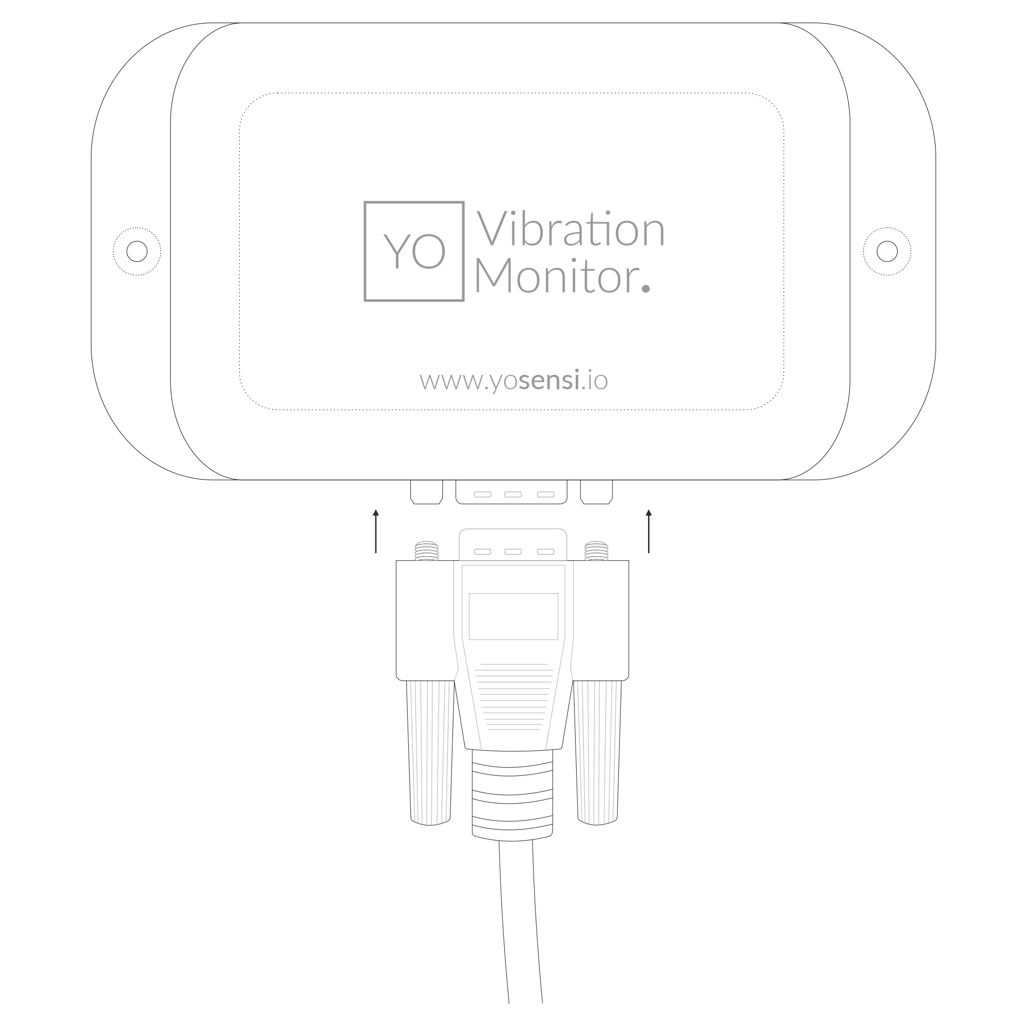
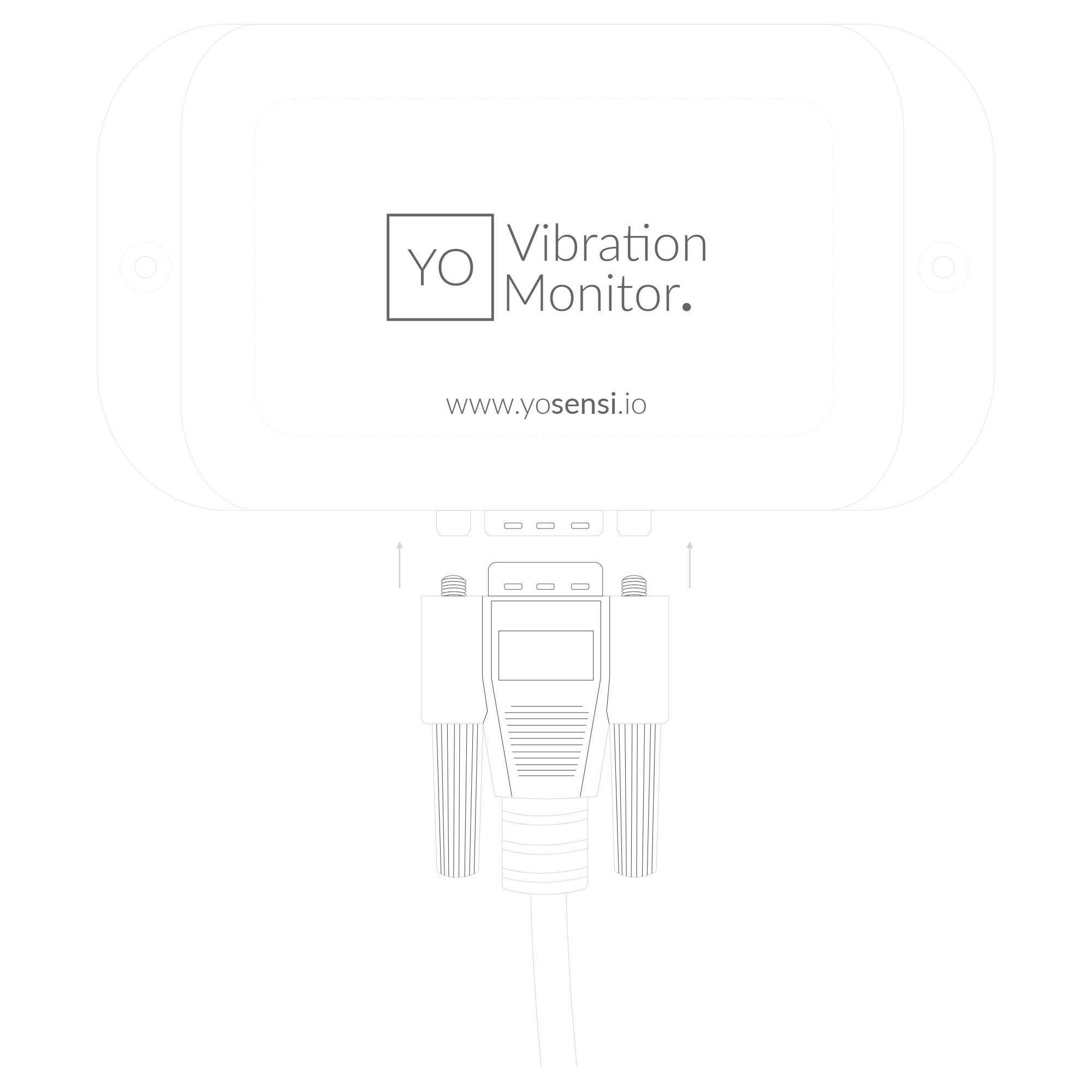
Figure 6. Connecting sensor to the device
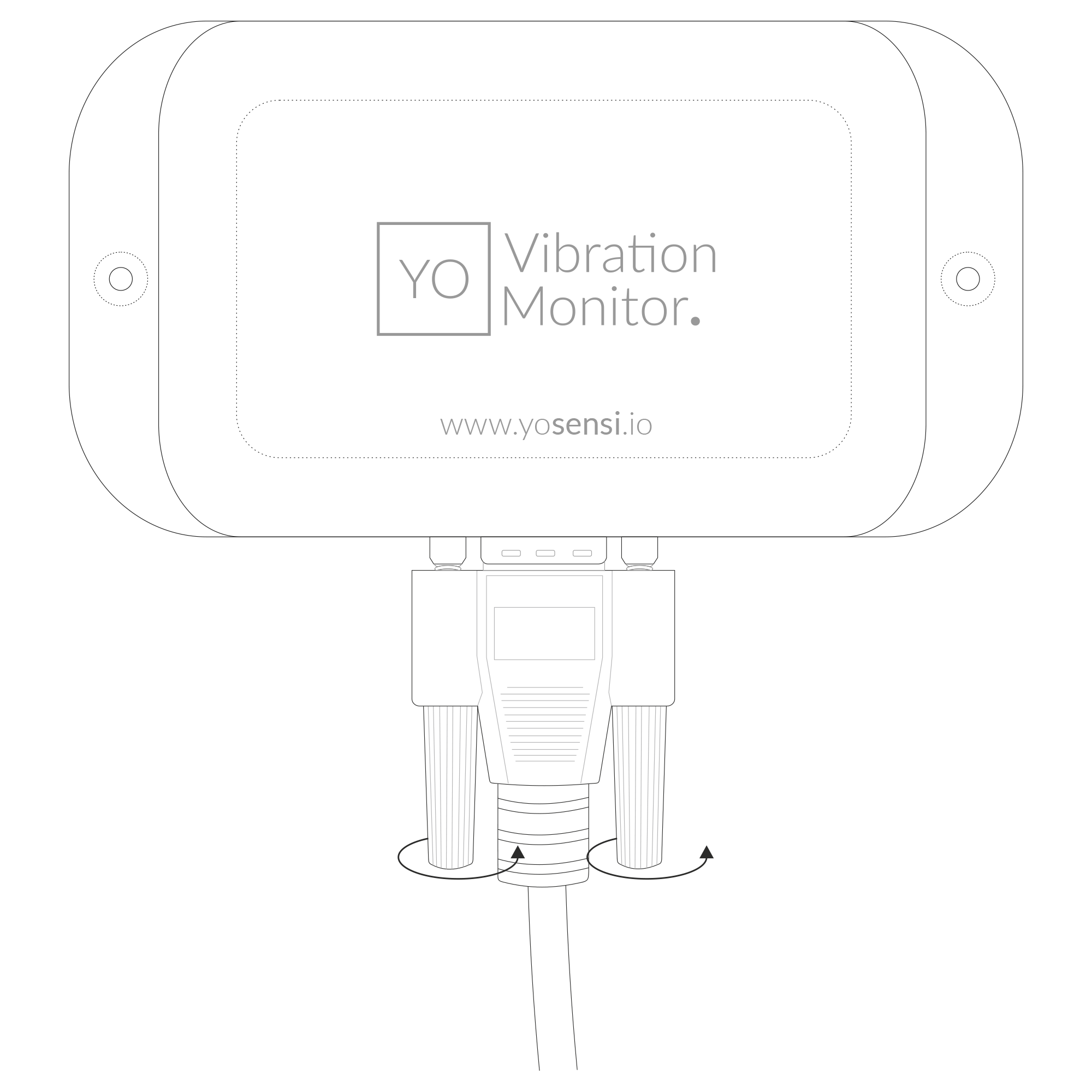
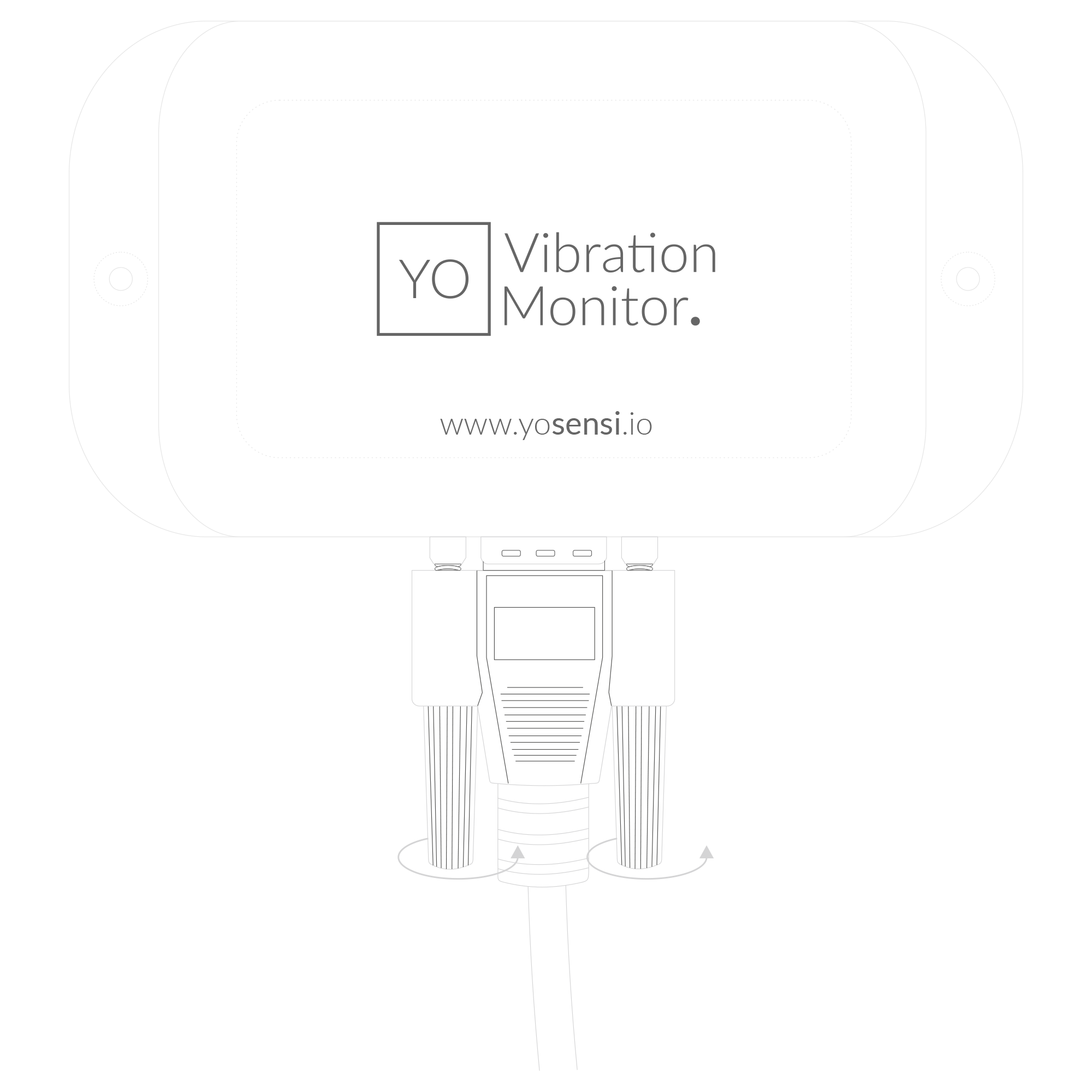
Figure 7. Tightening the sensor to the device
- Unscrew the device: remove 4 screws from the enclosure.
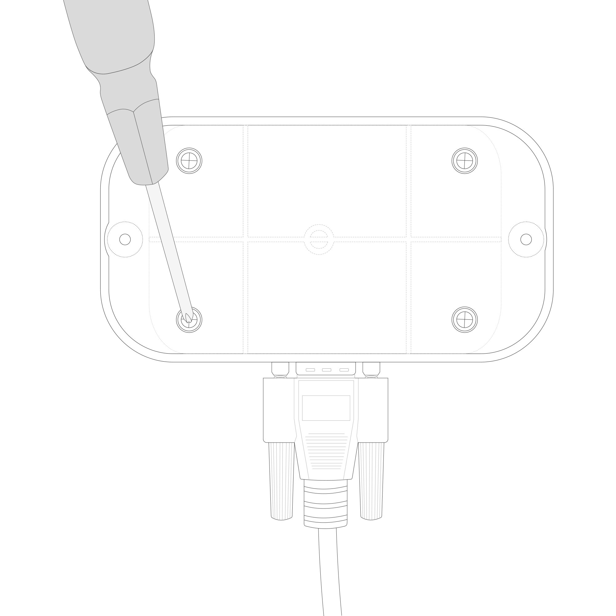
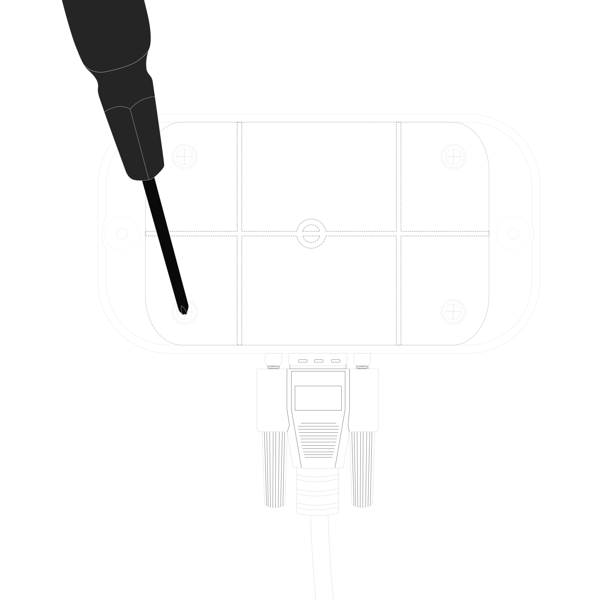
Figure 8. Back view of the device
- Place three LR6 (AA) batteries in the device according to the polarity indicated on the battery holder.
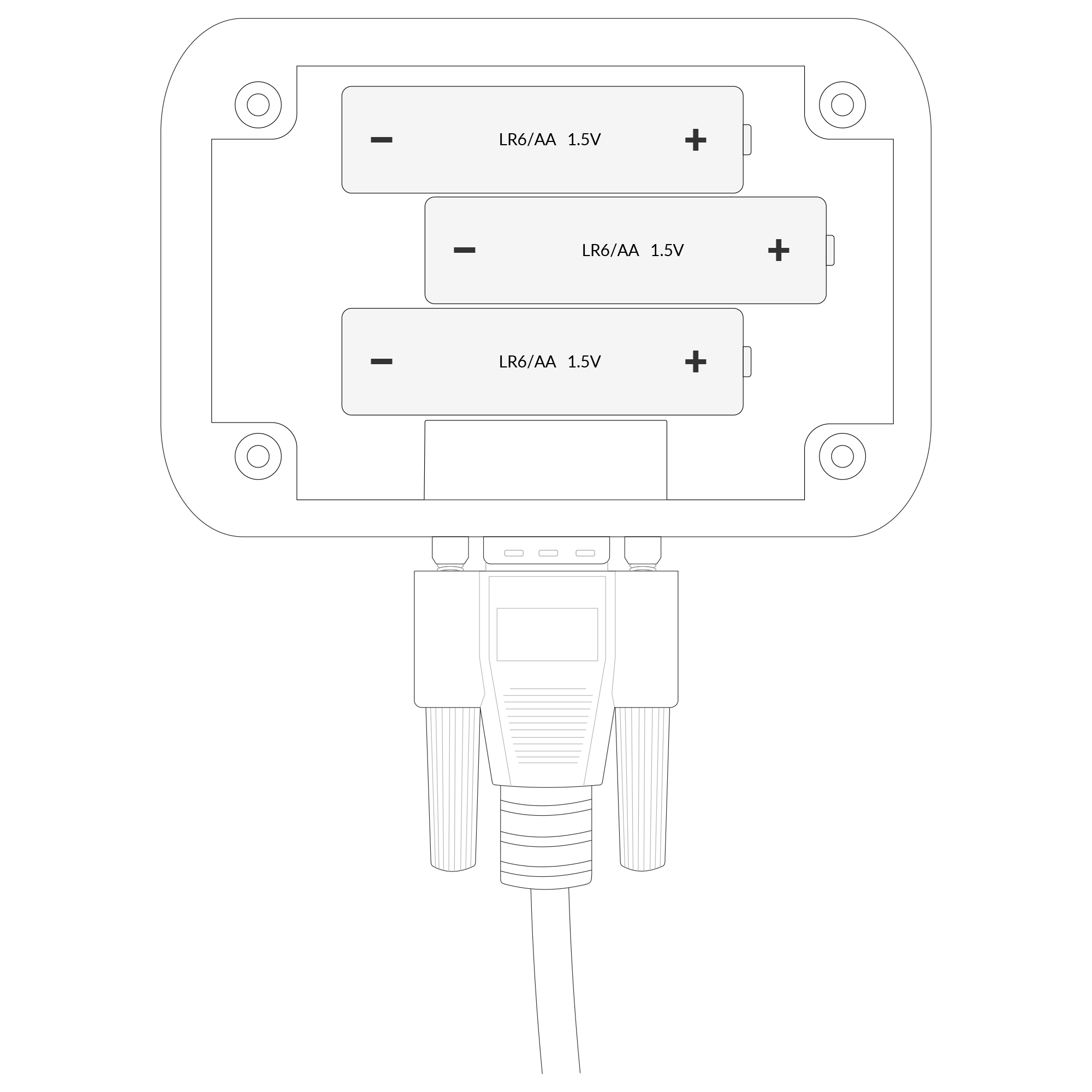
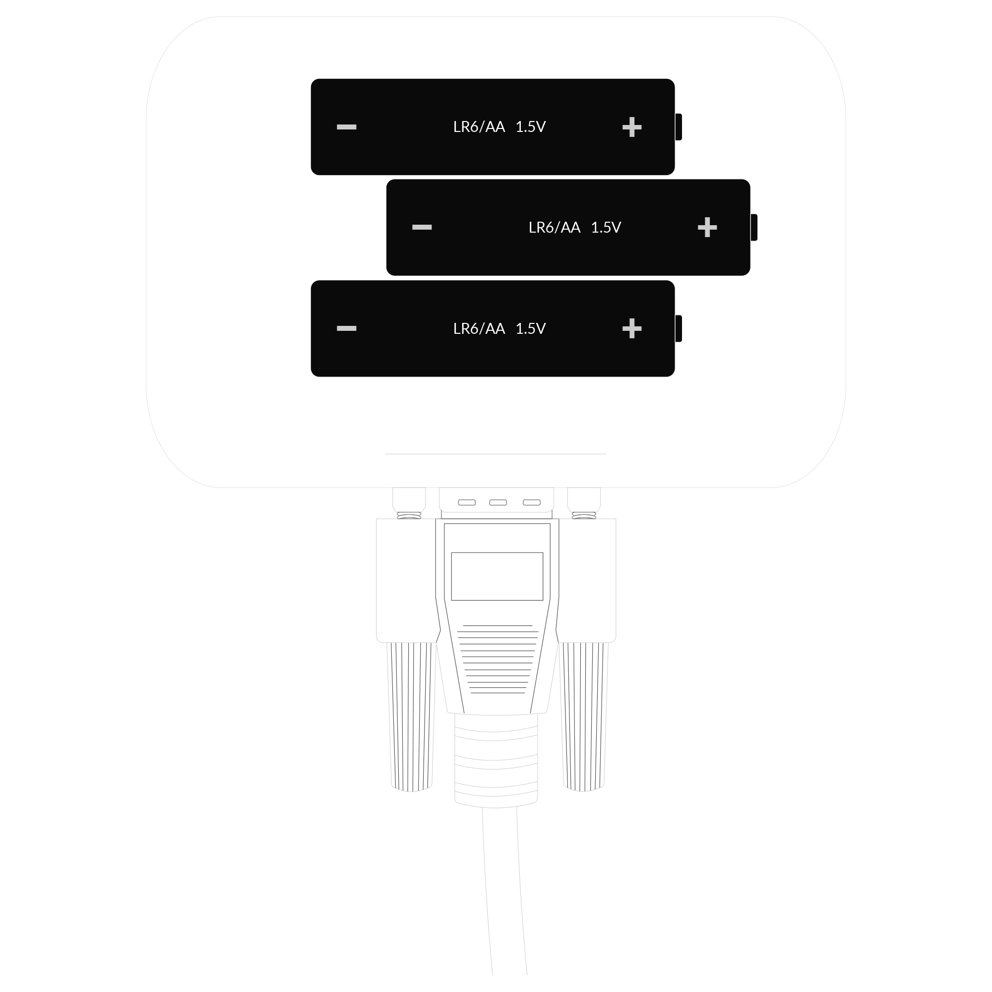
Figure 9. Battery placement instructions
-
Assemble the device and screw it back together.
-
The vibration sensor has an M5 thread. When placing an order, you can choose a different mounting option than the default one (magnet or external thread). Below are several recommended options for mounting the vibration sensor.
A. Magnet Mounting: Screw the magnet into the M5 thread. Attach the device to the metal surface of the electric motor according to the X, Y, Z axes marked on the sensor enclosure.
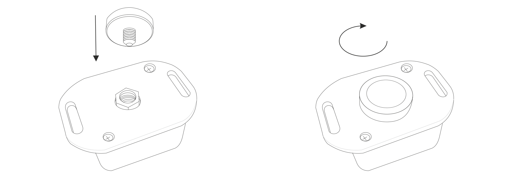
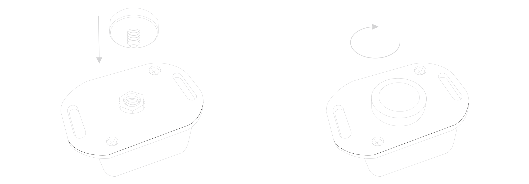
Figure 10. Magnet mounting view
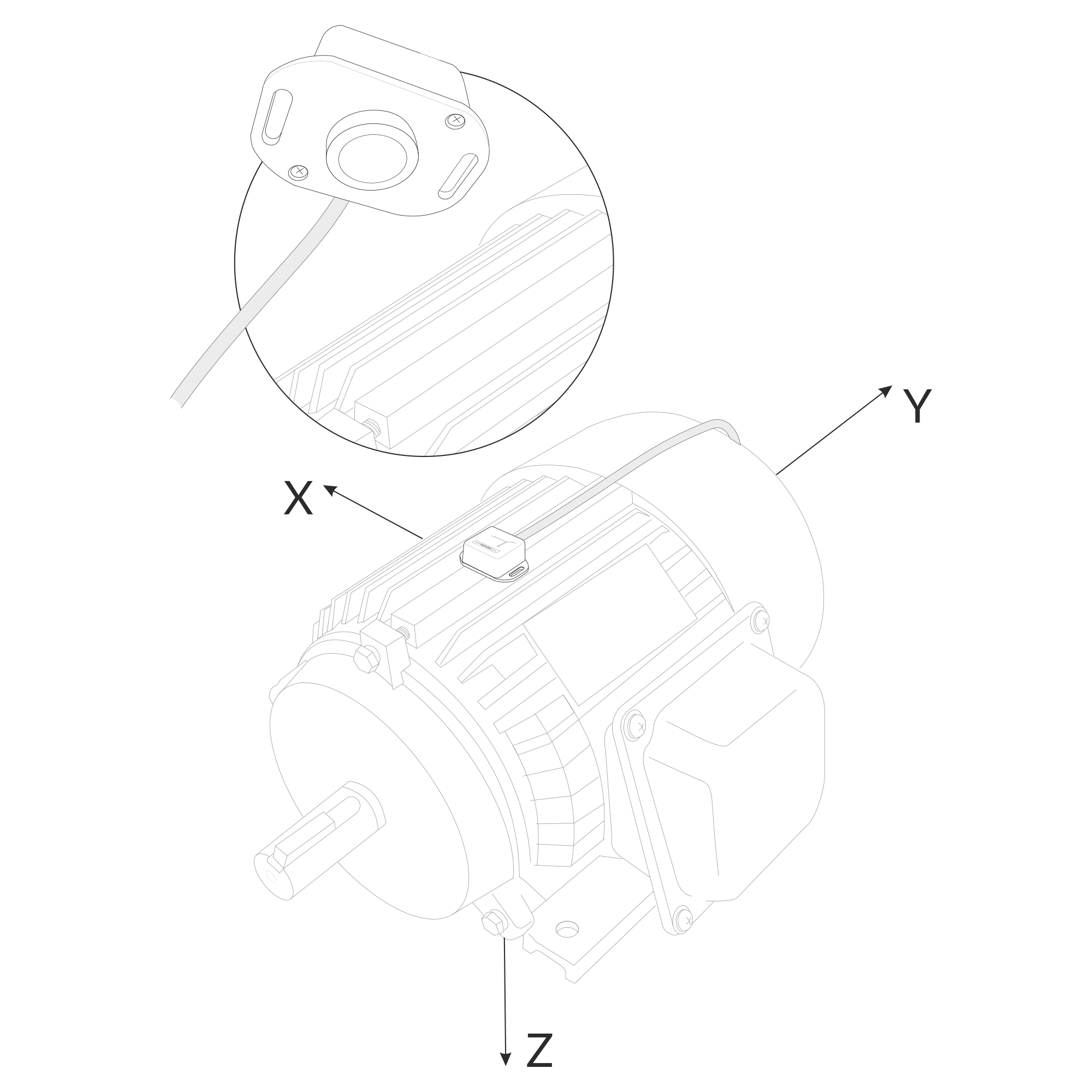
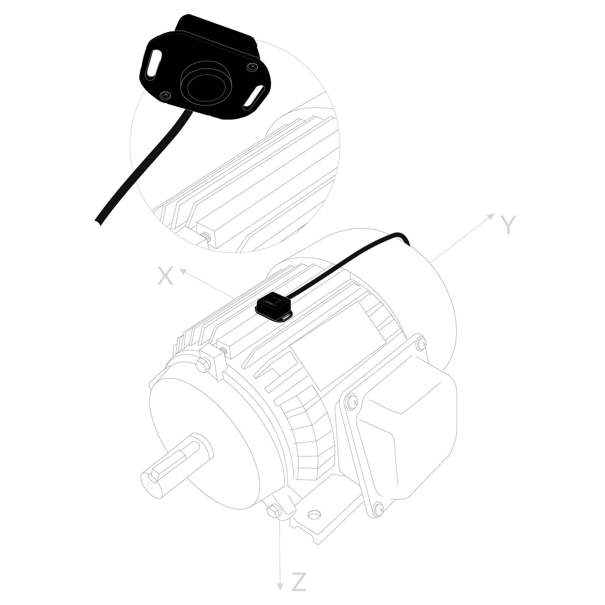
Figure 11. Magnet mounting view
B. Internal Thread Mounting: Attach a screw fitting the M5 thread to the surface of the motor and screw the vibration sensor into it according to the X, Y, Z axes marked on the sensor enclosure.
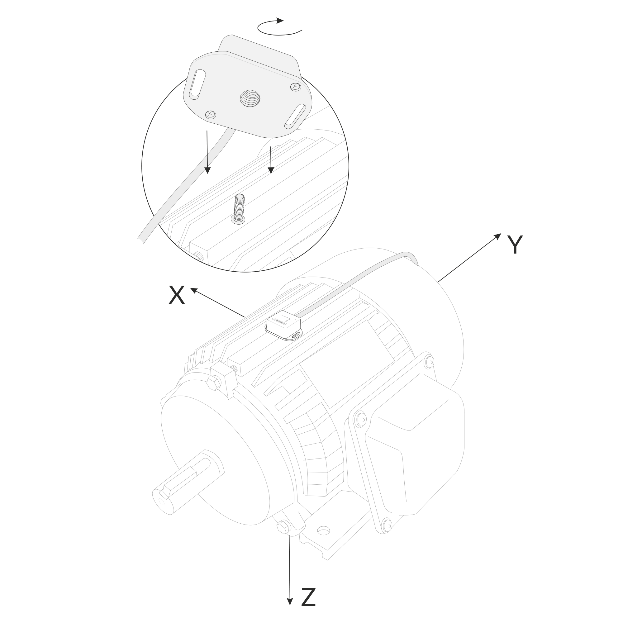
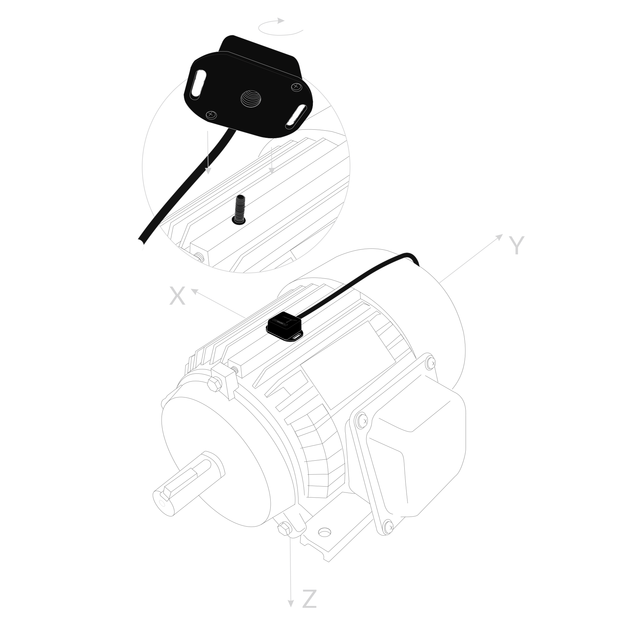
Figure 12. Internal thread mounting view
C. External Thread Mounting: Attach an M5 thread fitting the screw in the device to the surface of the motor. Mount the vibration sensor on the electric motor according to the X, Y, Z axes marked on the sensor enclosure.
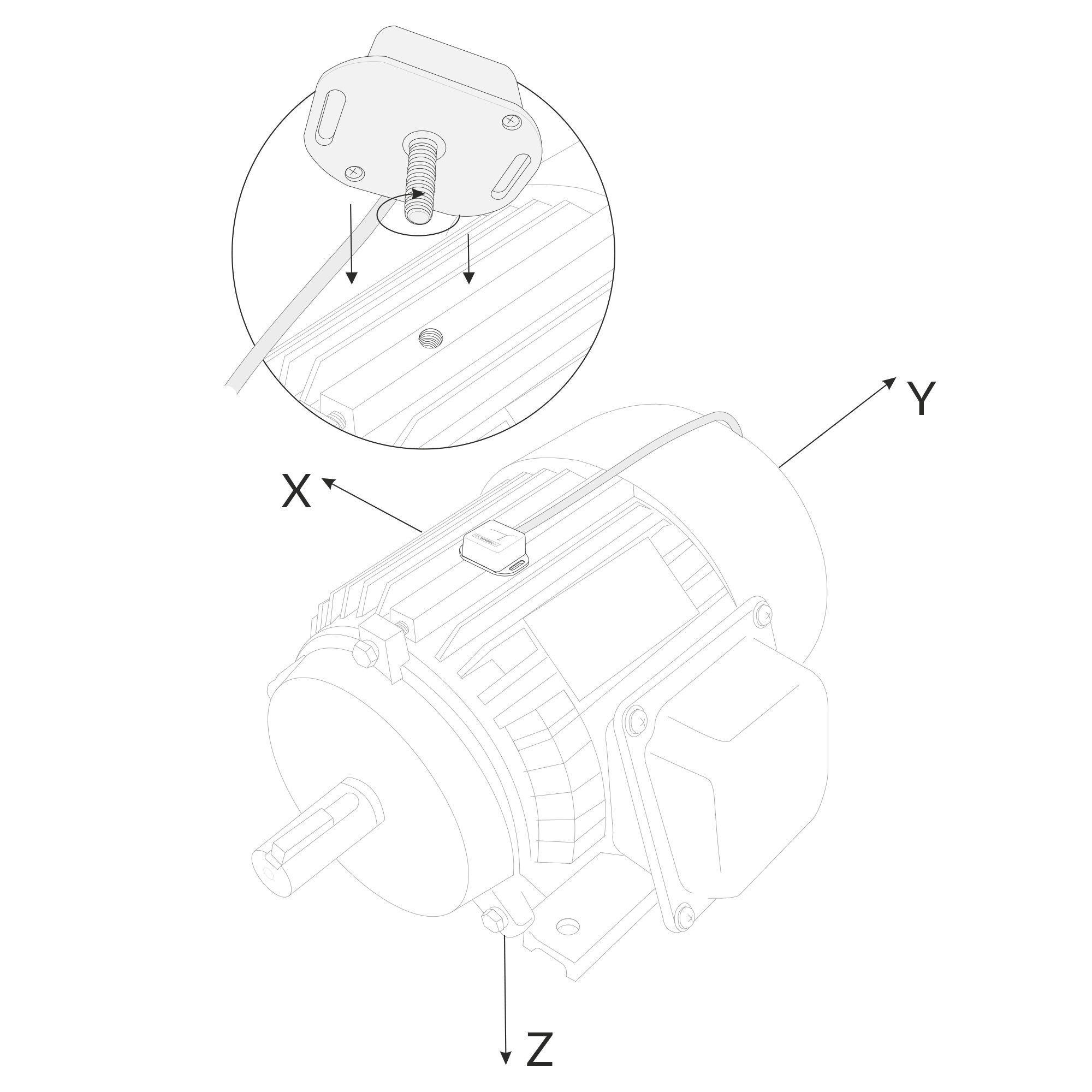
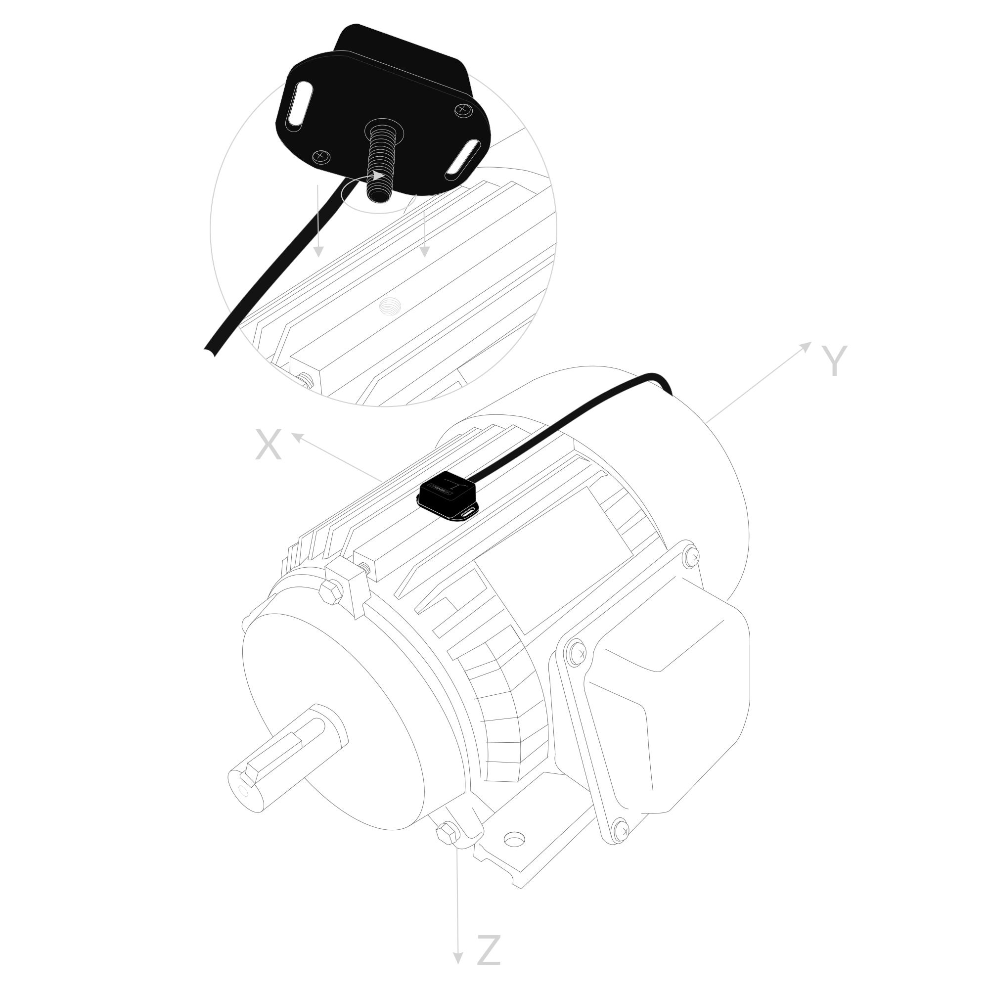
Figure 13. External thread mounting view
D. Mounting Bracket (Mounting Lugs): Using the mounting lugs on the enclosure, attach the vibration sensor to the electric motor with, for example, zip ties or screws. Remember to position the sensor according to the X, Y, Z axes marked on the sensor enclosure.
Configuration
Configurable Parameters
A few parameters must be set before sending data to the gateway. The default firmware is configured in OTAA mode with predefined deveui, appkey (OTAA) and appskey, nwkskey (ABP).
Configuration of the device is stored in a JSON file divided into the following sections:
- info (generic, read only): information about the device,
- general (generic): general device settings,
- lorawan (generic): configuration data for LoRaWAN connection,
- ble (generic): Bluetooth settings,
- device (dynamic): individual configuration for a specific device (this section’s structure differs for each device),
Sample configuration file for the YO Vibration Monitor device.
{
	"info": {
			"devmodel": "LNVM",
			"fwver": "1.2.1",
			"loraradio": "SX1261",
			"lorawanver": "1.0.2",
			"loraregion": "EU868",
			"blemacaddr": "0123456789ab"
	},
	"lorawan": {
			"subband": 1,
			"retrycnt": 3,
			"nwktype": "public",
			"acttype": "otaa",
			"otaa": {
					"deveui": "0123456789abcdef",
					"appeui": "be7a000000000688",
					"appkey": "000102030405060708090a0b0c0d0e0f",
					"trials": 3
			},
			"abp": {
					"devaddr": "01234567",
					"nwkskey": "0123456789abcdef0123456789abcdef",
					"appskey": "000102030405060708090a0b0c0d0e0f"
			}
	},
	"general": {
			"rtcstate": "disable",
	},
	"ble": {
			"power": 0,
			"interval": 1600
	},
	"device": {
			"measinterval": 3600,
    		"analysisfreqmax": 1000,
    		"analysisfreqmin": 10,
    		"vibrationdetector": {
      				"clearcnt": "no",
      				"threshold": "0.1g",
      				"activestate": "disable",
      				"delayvibrmeas": 10,
      				"inactivitytime": 60
    		}
	}
}
OTAA & ABP
| OTAA | ABP |
|---|---|
| Device EUI | Device Address |
| Application EUI | Network Session Key |
| Application Key | Application Session Key |
| Number of Trials |
Generic Parameters
Click here to see the generic parameters for Yosensi devices.
Parameters
Device Parameters
| Name | Description | Possible Values | Default Value | Read/Write |
|---|---|---|---|---|
| measinterval | Measuring and sending interval LoRa [s] | 601-999999 | 3600 | R/W |
| analysisfreqmax | Analysis Maximum Frequency | 1-10000 | 1000 | R/W |
| analysisfreqmin | Analysis Minimum Frequency | 1-10000 | 10 | R/W |
| clearcnt | Clear persistent counter | no/yes | no | R/W |
| threshold | Detector Threshold | 0.1-1.0 [g] | 0.1 | R/W |
| activestate | Vibration Detector State | disable/enable | disable | R/W |
| delayvibrmeas | Post-Detected Vibration Measurement Delay [s] | 1-999999 | 10 | R/W |
| inactivitytime | Debounce interval after detection [s] | 1-999999 | 60 | R/W |
| ||||
Parameters description
- rtcstate: used for enabling/disabling the real-time clock (RTC) inside the device. The RTC is used for timestamping the measurements.
- nwktype: used for setting the device in public or private network type.
- acttype: used for setting the device in ABP or OTAA mode.
- deveui, … , appskey: predefined addresses and keys, these parameters are generated using multiple IDs specific to the particular MCU and are unique for each device. They can be changed if needed.
- interval: determines the interval of sending broadcast packets, used to connect to every BLE receiver around the device.
- subband: used for setting the communication frequency sub-band in LoRaWAN.
- retrycnt: number of retries to send a LoRa packet if the acknowledgement is not received from the LoRaWAN server.
- measinterval: measurement interval [s] between sending LoRa packets.
- analysisfreqmax: maximum frequency [Hz] of the vibration analysis.
- analysisfreqmin: minimum frequency [Hz] of the vibration analysis.
- clearcnt: clears the persistent counter.
- threshold: threshold of vibration detection [g].
- activestate: enables/disables the vibration detection feature.
- delayvibrmeas: delay [s] of taking a measurement after detecting vibration above the threshold.
- inactivitytime: time [s] of inactivity after which the device rechecks the threshold, if it's still above the threshold, it waits again.
Downlink message
You can remotely adjust certain parameters by sending a downlink message through our platform. Simply navigate to the "COMMANDS" section for the selected device.
Change Measurement Interval
It is possible to change the measurement interval (measinterval) by using downlink. Information about changing the parameter will be sent from the server via the gateway.
Example of Downlink Message:
- Prefix:
0x03 - Measurement Index:
0x00 - Data (up to 4 bytes in hex):
0258
Sample Downlink: 0x03000258 - Sets a measurement interval of 600 seconds (10 minutes).
Click here to see how to connect a node using the Yosensi Management Platform.
See how to configure a node in Yosensi Management Platform
Check how to adopt and configure a node via the Yosensi App.
Take a look at the list of frequency plans used in Yosensi.
This datasheet describes the payload protocol developed by Yosensi for communicating with our devices.
Payload Decoder
If you want to connect to your own server, it is necessary to decode the specific payload for each device. To accomplish this, a payload decoder is required, which can be downloaded using the following link: Payload decoder. You can also use our integrated Payload Decoder here. Extended documentation of the protocol can be found in the Payload description on our website.
Compliance Statements
To view or download the Declaration of Conformity for YO Vibration Monitor go here