YO Leak Guard
Overview
Description
YO Leak Guard is a LoRaWAN device for detecting leaks of conductive liquids such as water, weak acids and weak alkaline liquids. The device has two independent leak detection channels. Each channel uses a sensing cable that triggers an alarm when liquid touches it at any point along its length. The sensing cable is connected to the device with a non-sensing lead cable, so the device can be installed away from the monitored area. The device also reports when a sensing cable is disconnected. Additionally, the device measures temperature and relative humidity inside its enclosure.
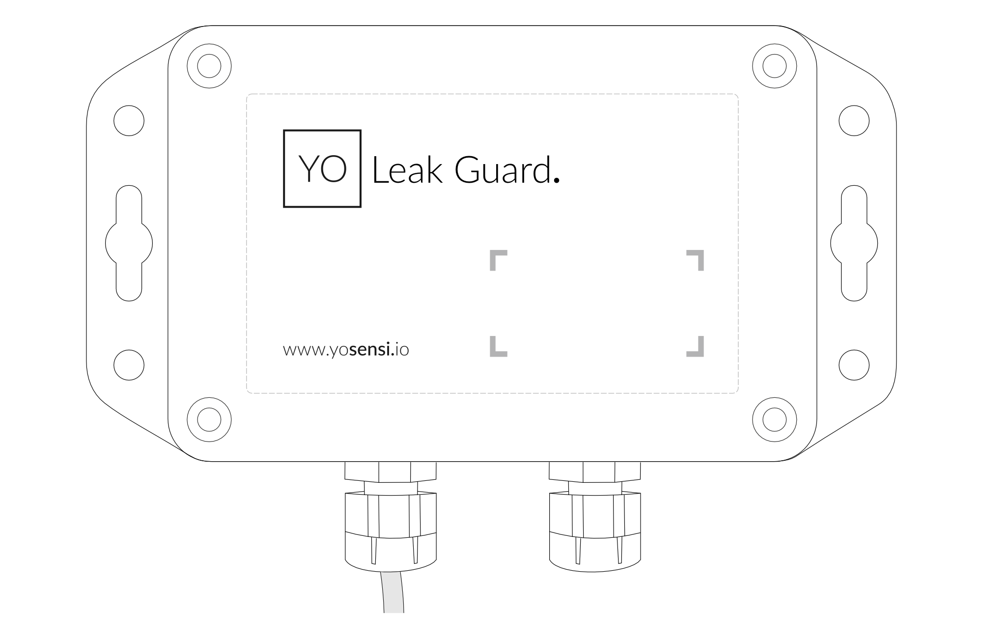
Figure 1. Device top view
Device sticker placed on the right side of the device enclosure contains information about model, version, LoRaWAN region and 3 parameters important in case of device identification and configuration:
- DEV EUI: 64-bit unique device identifier in a LoRaWAN network,
- DEV ADDR: address required to connect via ABP activation type to LoRaWAN,
- BLE MAC: Bluetooth physical address.
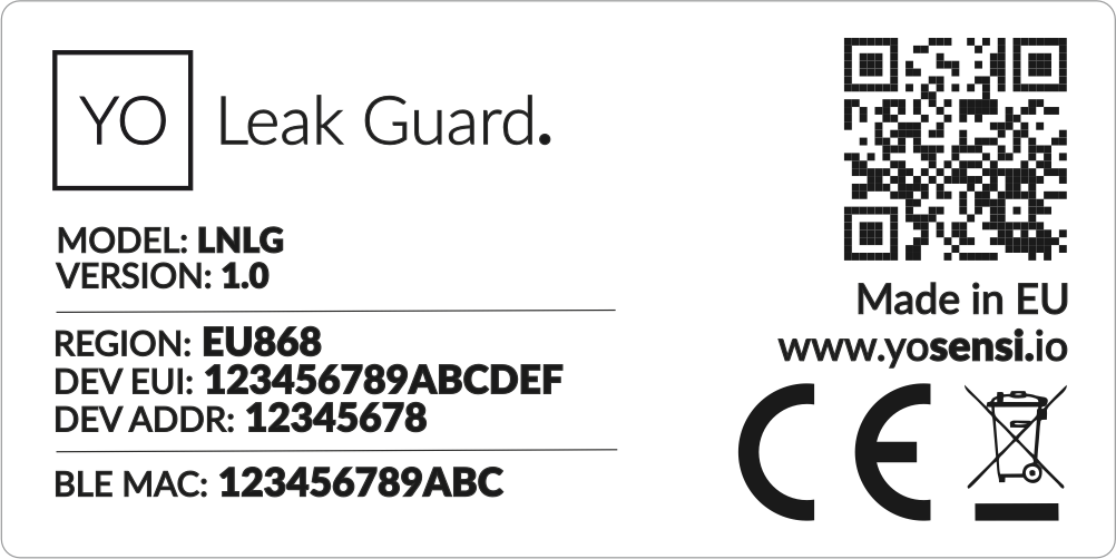
Figure 2. Device sticker
Features
- LoRaWAN Technology: Available in multiple versions with LoRa radio configured for various regions and ISM frequency bands (e.g., EU868, US915, AU915, AS923), it is compatible with both private and public LoRaWAN networks and supports connections via ABP (Activation by Personalization) or OTAA (Over-The-Air Activation).
- Bluetooth Low Energy (BLE): Enables easy configuration through a user-friendly JSON data exchange format, supports firmware updates via OTA (Over-the-Air), and boasts very low energy consumption.
- Battery-Powered: 3x AA batteries, either alkaline 1.5 V (LR6) or lithium 3.6 V featuring very low self-discharge, ensuring long-term operation without the need for an external power supply.
- Two Independent Leak Detection Channels: Each channel has its own sensing cable, so one device can monitor two separate areas.
- Leak Detection Along the Whole Cable: The sensing cable detects liquid at any point along its length, covering a much larger area than a single-point sensor.
- Fast Response and Automatic Reset: The sensing cable responds to a leak in less than 1 minute and returns to normal operation once it is dry, so it can be reused after a leak.
- Cable Disconnection Detection: The device reports when a sensing cable is not connected.
- Low False Alarm Rate: The spiral structure of the sensing cable reduces interference and false alarms.
- Plug-and-Play Cables: Both cables are equipped with quick-connect terminals, making installation easy.
- Temperature and Relative Humidity: Measures temperature and relative humidity within the device enclosure, providing valuable insights into the surrounding environment.
- IP 67 and IK08 Protection: The robust enclosure ensures the device is dust-tight and protected against water immersion up to 1 meter for 30 minutes, as well as resistant to mechanical impacts, making it suitable for harsh environments.
- Yosensi Management Platform: Provides a web tool for device configuration, firmware updates, and infrastructure management. Enables comprehensive monitoring of transmitted data and easy device management.
- Yosensi Mobile App: Effortlessly manage devices with features to register new ones, configure settings, perform firmware updates, view/send logs, and test LoRaWAN connectivity. Learn more in our detailed Yosensi App blog post.
Specifications
Physical
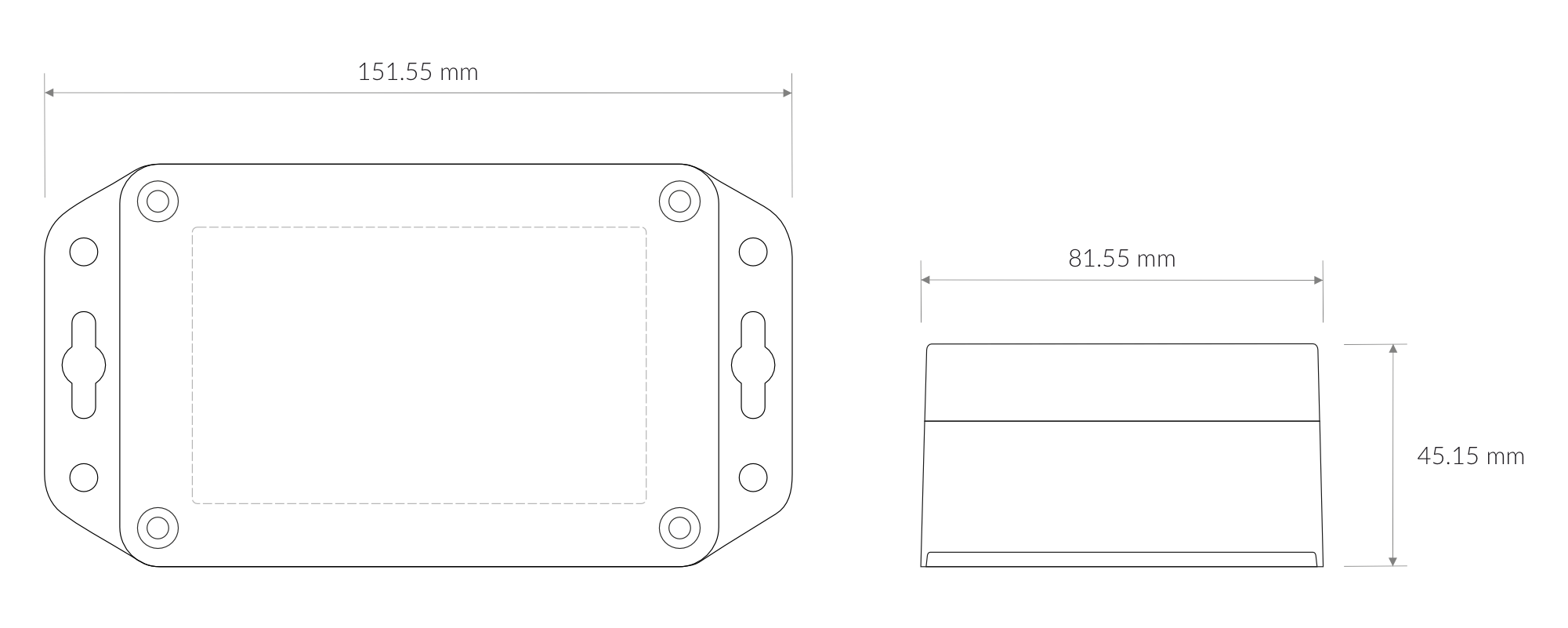
Figure 3. Dimensions of the device
Device
| Attribute | Description |
|---|---|
| Dimensions | Height: 45.15 mm Width: 81.55 mm Depth: 151.55 mm |
| Colour | Light Grey |
| Mounting method | Horizontal Vertical (can be screwed to the wall) |
| Enclosure material | Polycarbonate |
| Level of protection | IP67, IK08 |
| Weight (without batteries, excl. cables) | 215 g |
| Weight (with batteries, excl. cables) | 270 g |
Leak Sensing Cable
| Attribute | Description |
|---|---|
| Number of channels | 2 (independent) |
| Included with the cable | Waterproof terminator |
| Cable length | Depends on the ordered cable (standard length: 5 m) |
| Cable extension | Multiple sensing cables can be connected together to extend the monitored length |
| Cable material | Conductive polyethylene + alloy conductor |
| Core resistance | 13 Ω / 100 m |
| Colour | Yellow |
| Cable diameter | 6 mm |
| Breaking strength | 60 kg |
| Weight | 43 g/m |
| Maximum exposure temperature | 85°C |
| Response time | < 1 min |
| Detected liquids | Conductive liquids: water, weak acids, weak alkaline liquids |
| Not suitable for | Hazardous chemicals, solvents, oil, fuel, strong acids and other corrosive liquids |
| Leak location | Detected anywhere along the cable (the exact position of the leak is not reported) |
| Detection threshold | Water covering ≥ 3 cm of the cable at a depth of ≥ 1 mm (adjustable with the ch1sensitivity / ch2sensitivity parameters) |
| Connection | Quick-connect terminals on both ends |
Lead Cable
The lead cable is a non-sensing cable that connects the device to the leak sensing cable. It does not react to liquids, which allows the device to be installed outside the monitored area.
| Attribute | Description |
|---|---|
| Cable length | Depends on the ordered cable (standard length: 5 m) |
| Cable extension | Multiple lead cables can be connected together to increase the distance between the device and the sensing cable |
| Function | Non-sensing connection between the device and the leak sensing cable |
| Connection | Quick-connect terminal on the sensing cable side |
Operating Conditions
| Attribute | Description |
|---|---|
| Temperature | 0°C to 70°C |
| Humidity | 0 to 90% |
| Placement | Indoor/Outdoor use |
| Power supply | 3 x LR6 (AA) alkaline battery (3 x 1.5 V) or 3 x AA lithium battery (3 x 3.6 V) |
| Power consumption | Maximum: 120 mA DC (4.5 V DC, alkaline) / 120 mA DC (10.8 V DC, lithium) |
Measured Values
| Parameter | Measurement range | Accuracy |
|---|---|---|
| Temperature (internal) | -40°C to 125°C | ±0.2°C (5°C to 60°C) |
| Relative humidity (internal) | 0% to 100% | ±2% (20% to 80%) |
| Leak state (per channel) | 0-3 (0 - dry, 1 - leak detected, 2 - cable not detected, 3 - not calibrated) | - |
Leak State Reporting
The device checks both leak detection channels every minute, independently of the measurement interval (measinterval). Temperature, relative humidity and both leak states are also sent periodically with every measurement interval.
- State change: when the leak state of a channel changes (e.g. a leak is detected or the cable dries), the device sends the data immediately.
- Leak detected (1): while a leak is present, the device repeats the message about every 3 minutes until the cable is dry.
- Cable not detected (2): the sensing cable, its waterproof terminator or the lead cable is disconnected or damaged.
- Not calibrated (3): the device has not yet measured the dry cable reference for the channel. See Calibration.
Controls and Indicators
LED Status Indicator
YO Leak Guard communicates its current behaviour to the user by RGBW LED placed on the top.
Diode statuses interpretation
The LED does not indicate the leak state. Leak states are reported over LoRaWAN only.
| Behavior | Colour | Status |
|---|---|---|
| Single flash | Green | General: device is working correctly (power and memory). |
| Single flash | Red | General: device is working incorrectly (power and memory). LoRaWAN communication: failed to receive an acknowledgement from LoRaWAN Server within specified timeout. |
| Single flash | White | LoRaWAN communication: LoRaWAN frame sent / confirmation from LoRaWAN Server after receiving the frame. |
| Slow flashing | Blue | BLE communication: connection to the device via BLE (configuration). |
| Rapid flashing | Blue | LoRaWAN communication: connecting to LoRaWAN network. |
Buttons
The YO Leak Guard features a reset button located on the PCB, labeled "Reset". To reboot the device, simply press the button briefly.
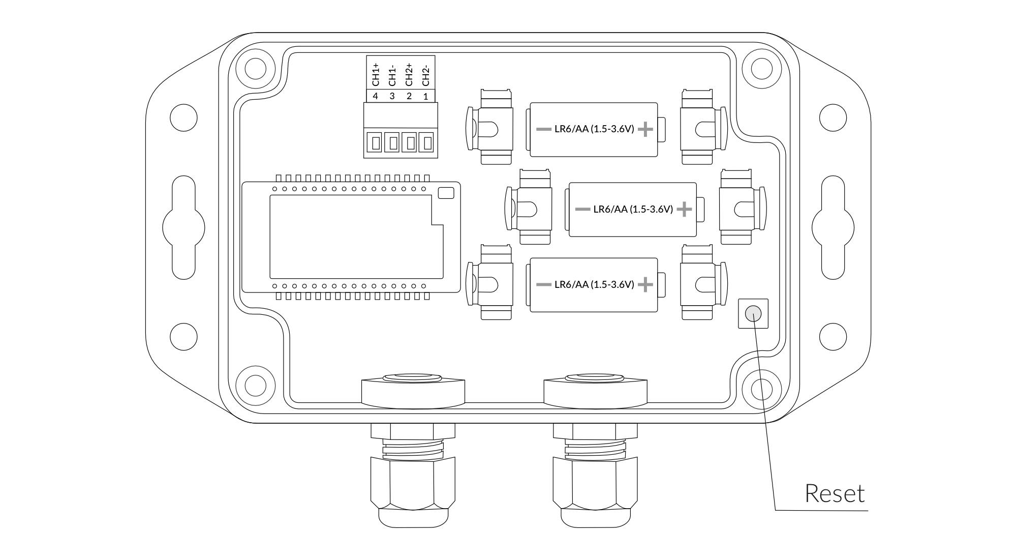
Figure 4. Reset button
Installation
Package Contents
- Device (without batteries).
- Warranty card.
Lead cables and leak sensing cables are not included with the device. Each sensing cable comes with a waterproof terminator.
Safety Precautions
Go to the Safety Precautions section to see important information on handling, disposal and maintenance.
Setup Overview
The figure below shows an example setup. The device is connected to the leak sensing cable through a non-sensing lead cable, so it can be mounted outside the monitored area. Further sensing cables or lead cables can be connected in a chain, and the free end of the last sensing cable is closed with the waterproof terminator. Leak states are sent over LoRaWAN to the Yosensi Platform and can be monitored in the mobile app.
The figure also shows the typical sensing cable layouts and the recommended and not recommended ways to secure the cable (see steps 6 and 7 of the Installation Guide).
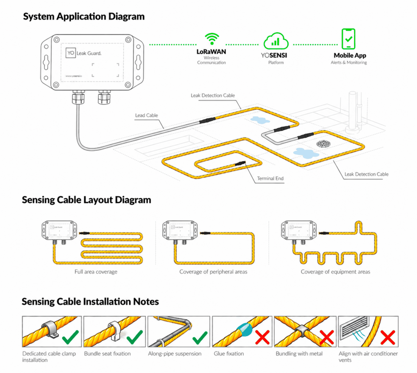
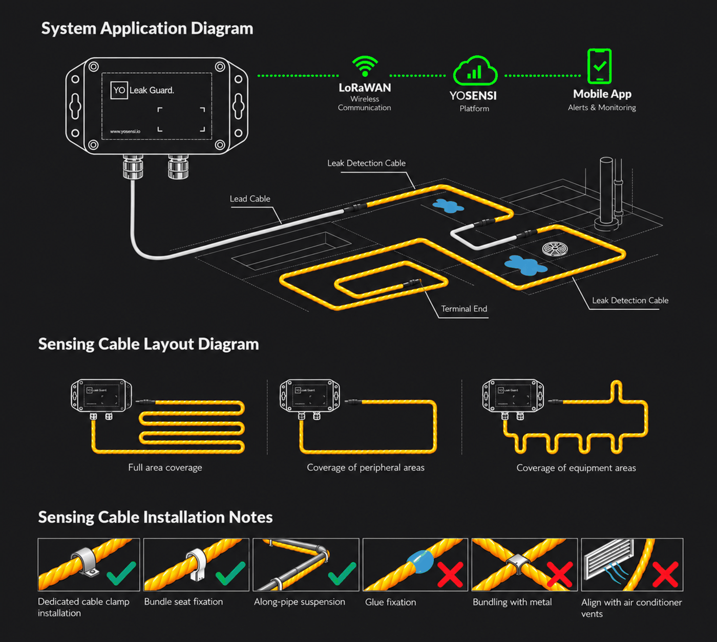
Figure 5. Example setup and sensing cable layouts (click to enlarge)
Installation Guide
- Unscrew the device: remove 4 screws from the enclosure.
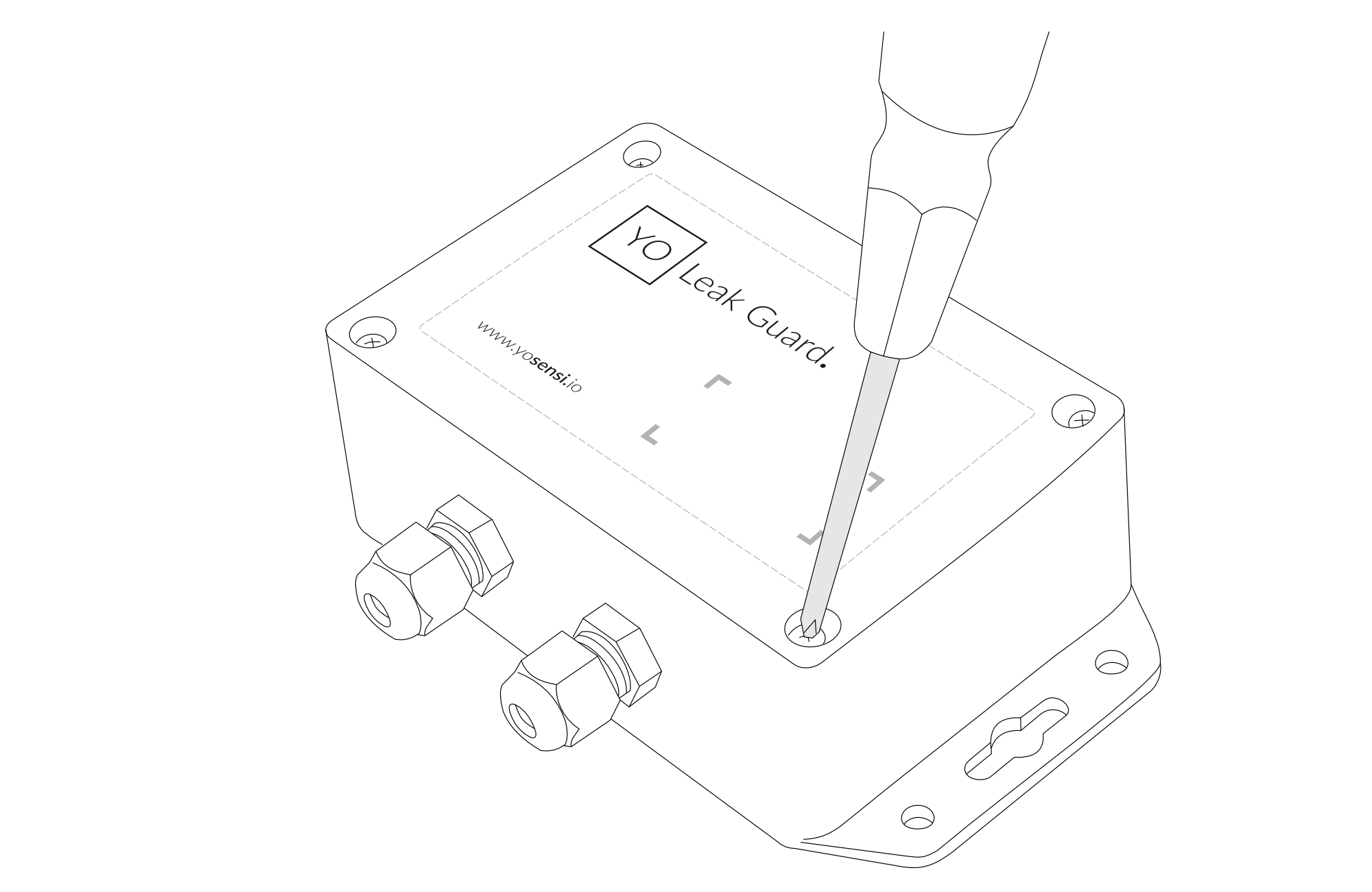
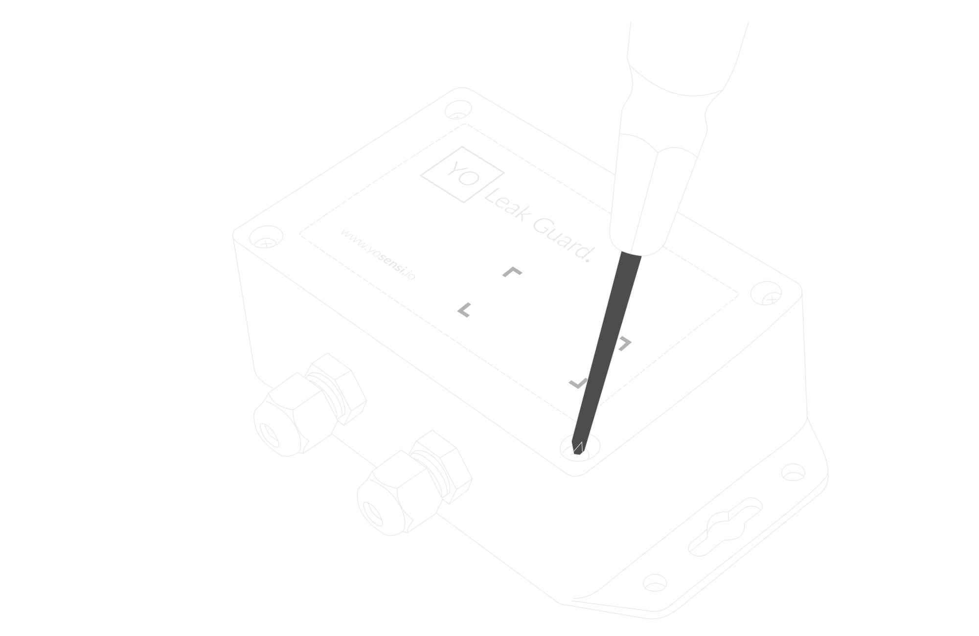
Figure 6. Unscrewing the device top cover
- Pass the lead cable through the cable gland.
Inside the device, connect the two wires of the lead cable to the CH1+ and CH1- terminals of the green push-in connector. If you use the second channel, connect its lead cable to CH2+ and CH2-, passing it through the second cable gland.
Push each wire firmly into its terminal until it is held in place. No tools are needed.
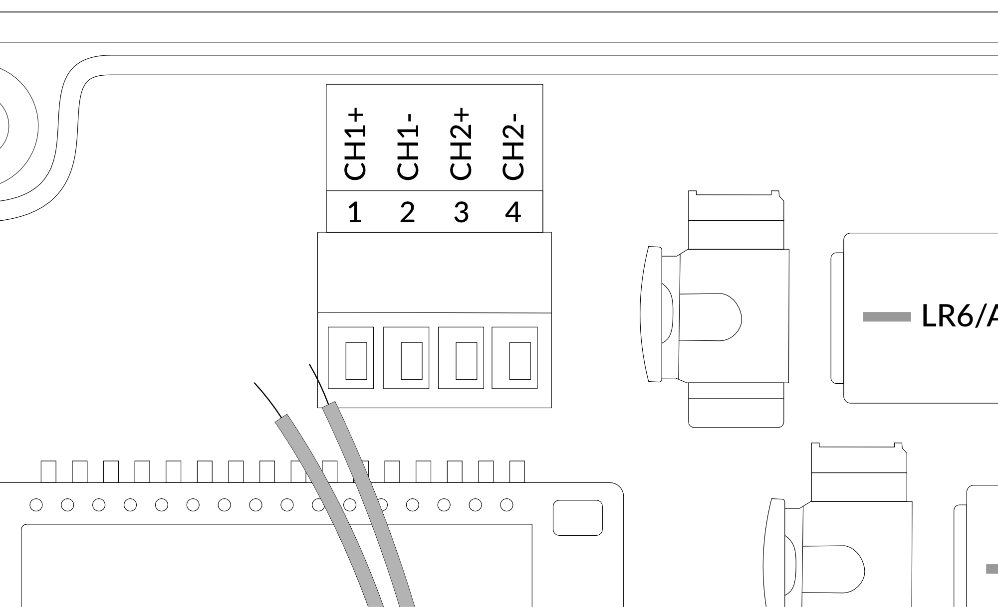
Figure 7. Lead cable passing through the cable gland instructions
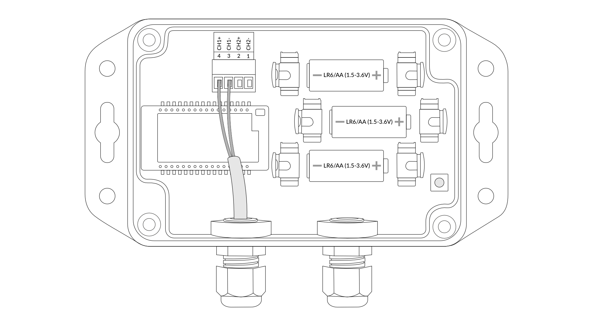
Figure 8. Lead cable connected to channel 1
- Connect the leak sensing cable to the quick-connect terminal at the end of the lead cable. To extend the monitored length, connect further sensing cables to the end of the first one. Fit the waterproof terminator to the free end of the last sensing cable.
Connect the sensing cable with its waterproof terminator, and make sure the cable is clean and dry, before inserting the batteries. The device measures the dry cable reference right after start-up (see Calibration).
- Place three AA batteries (LR6 1.5 V alkaline or 3.6 V lithium) in the device according to the polarity indicated on the battery holder.
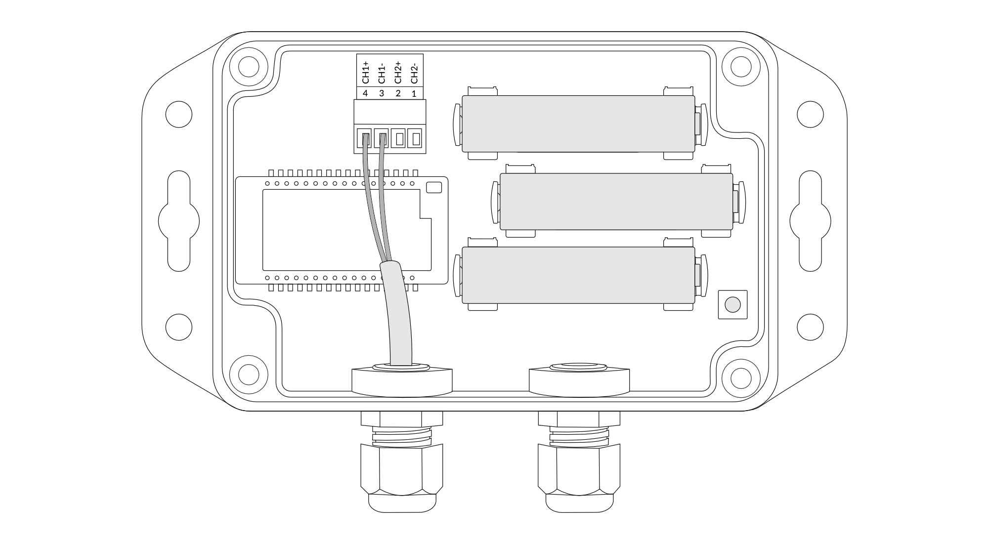
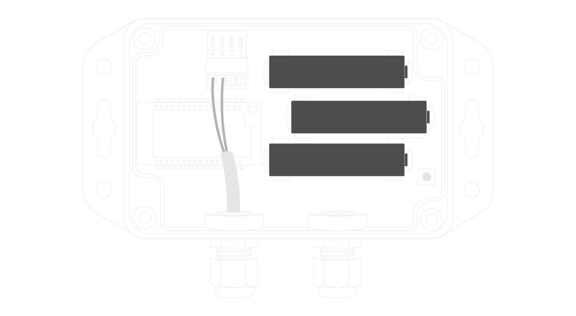
Figure 9. Battery placement instructions
-
Assemble the device and screw it back together.
-
Lay the leak sensing cable flat on the floor in the area to be monitored. Depending on the needs, the cable can be laid out in several ways (see Figure 5):
- Full area coverage: the cable is laid in a serpentine pattern across the whole floor area.
- Perimeter coverage: the cable runs along the edges of the room or area.
- Equipment coverage: the cable is laid around or underneath equipment that may leak (e.g. air conditioning units, pumps, tanks, water heaters).
-
Secure the leak sensing cable (see Figure 5):
- Recommended: use dedicated cable clips, secure the cable with cable ties, or suspend it along pipes.
- Not recommended: do not fix the cable with glue, do not bind it with metal, and do not place it directly under air conditioning vents, as this may cause false alarms or damage the cable.
- Lay the cable flat and tight to the surface. When running it around pipes, do not twist or bunch it up.
- Keep the cable away from foot traffic, sharp objects and heavy items that could roll or drop onto it.
- Keep the cable away from air conditioning outlets and damp places, and keep the cable connectors out of water, to avoid false alarms.
-
Install the device away from metal objects and other obstacles for the best LoRaWAN signal.
After a leak, the sensing cable returns to normal operation automatically once it is dry. Make sure the cable is clean and dry, and that the leak state is back to 0 (dry), before putting it back into operation.
Cleaning the Sensing Cable
To clean the sensing cable, disconnect it from the lead cable, wipe it with alcohol or soapy water, and hang it up to dry completely before connecting it again.
Calibration
Each leak detection channel needs a reference measurement of its dry cable. The device takes it automatically after start-up for every channel that is not calibrated yet. The calibration takes about 25 seconds, during which the cable must stay dry and must not be moved.
- If the cable is wet, not connected, or the readings are unstable, the calibration is not saved. The device retries it with every measurement interval and reports leak state 3 (not calibrated) in the meantime.
- When the calibration is done, the
ch1calibration/ch2calibrationparameter changes todone. - Calibrate the channel again whenever you change its cable setup (e.g. connect a different or additional sensing cable or lead cable): set
ch1calibration/ch2calibrationtostart.
Configuration
Configurable Parameters
A few parameters must be set before sending data to the gateway. The default firmware is configured in OTAA mode with predefined deveui, appkey (OTAA) and appskey, nwkskey (ABP).
Configuration of the device is stored in a JSON file divided into the following sections:
- info (generic, read only): information about the device,
- general (generic): general device settings,
- lorawan (generic): configuration data for LoRaWAN connection,
- ble (generic): Bluetooth settings,
- device (dynamic): individual configuration for a specific device (this section’s structure differs for each device),
Sample configuration file for the YO Leak Guard device.
{
	"info": {
		"devmodel": "LNLG",
		"fwver": "1.0.0",
		"loraradio": "SX1261",
		"lorawanver": "1.0.2",
		"loraregion": "EU868",
		"blemacaddr": "0123456789ab"
	},
	"general": {
		"rtcstate": "disable",
		"periodicreboot": 14
	},
	"lorawan": {
		"subband": 1,
		"retrycnt": 1,
		"nwktype": "public",
		"acttype": "otaa",
		"otaa": {
			"deveui": "0123456789abcdef",
			"appeui": "fedcba9876543210",
			"appkey": "000102030405060708090a0b0c0d0e0f",
			"trials": 3
		},
		"abp": {
			"devaddr": "01234567",
			"nwkskey": "0123456789abcdef0123456789abcdef",
			"appskey": "000102030405060708090a0b0c0d0e0f"
		}
	},
	"ble": {
		"power": 0,
		"interval": 1600
	},
	"device": {
		"measinterval": 3600,
		"ch1sensitivity": 6,
		"ch2sensitivity": 6,
		"ch1calibration": "done",
		"ch2calibration": "done"
	}
}
OTAA & ABP
| OTAA | ABP |
|---|---|
| Device EUI | Device Address |
| Application EUI | Network Session Key |
| Application Key | Application Session Key |
| Number of Trials |
Generic Parameters
Click here to see the generic parameters for Yosensi devices.
Parameters
Device Parameters
| Name | Description | Possible Values | Default Value | Read/Write |
|---|---|---|---|---|
| measinterval | Measuring and sending interval LoRa [s] | 601-999999 | 3600 | R/W |
| ch1sensitivity | Leak detection sensitivity of channel 1 (10 - the most sensitive) | 1-10 | 6 | R/W |
| ch2sensitivity | Leak detection sensitivity of channel 2 (10 - the most sensitive) | 1-10 | 6 | R/W |
| ch1calibration | Dry cable reference measurement of channel 1 | "start", "done" | "start" | R/W |
| ch2calibration | Dry cable reference measurement of channel 2 | "start", "done" | "start" | R/W |
| ||||
Parameters description
- rtcstate: used for enabling/disabling the real-time clock (RTC) inside the device. The RTC is used for timestamping the measurements.
- periodicreboot: number of days of continuous operation after which the device reboots preventively (0-60, 0 - disabled, default 14).
- nwktype: used for setting the device in public or private network type.
- acttype: used for setting the device in ABP or OTAA mode.
- deveui, … , appskey: predefined addresses and keys, these parameters are generated using multiple IDs specific to the particular MCU and are unique for each device. They can be changed if needed.
- interval: determines the interval of sending broadcast packets, used to connect to every BLE receiver around the device.
- subband: used for setting the communication frequency sub-band in LoRaWAN.
- retrycnt: number of retries to send a LoRa packet if the acknowledgement is not received from the LoRaWAN server.
- measinterval: measurement interval [s] between sending LoRa packets. Leak states are checked every minute regardless of this value, see Leak State Reporting.
- ch1sensitivity, ch2sensitivity: leak detection sensitivity of the channel. A higher value triggers the alarm with less liquid on the cable.
- ch1calibration, ch2calibration: set to
startto measure the dry cable reference of the channel again. The device changes the value todoneafter a successful calibration, see Calibration.
Downlink message
You can remotely adjust certain parameters by sending a downlink message through our platform. Simply navigate to the "COMMANDS" section for the selected device.
Update Measurement Interval
It is possible to change the measurement interval (measinterval) by using downlink. Information about changing the parameter will be sent from the server via the gateway.
Example of Downlink Message:
- Prefix:
0x03 - Measurement Index:
0x00 - Data (up to 4 bytes in hex):
0258
Sample Downlink: 0x03000258 - Sets a measurement interval of 600 seconds (10 minutes).
Click here to see how to connect a node using the Yosensi Management Platform.
See how to configure a node in Yosensi Management Platform
Check how to adopt and configure a node via the Yosensi App.
Take a look at the list of frequency plans used in Yosensi.
This datasheet describes the payload protocol developed by Yosensi for communicating with our devices.
Payload Decoder
If you want to connect to your own server, it is necessary to decode the specific payload for each device. To accomplish this, a payload decoder is required, which can be downloaded using the following link: Payload decoder. You can also use our integrated Payload Decoder here. Extended documentation of the protocol can be found in the Payload description on our website.